Vehicle camera with lens washer system

a technology of vehicle camera and lens washer, which is applied in the field of vehicle camera with lens washer system, can solve the problems of increasing the cost of assembly process at the system supplier, reducing the available area of engine air flow through the front grille, and obscuring the view of mud, salt or dus

Inactive Publication Date: 2016-09-22
MAGNA ELECTRONICS
View PDF8 Cites 94 Cited by
  • Summary
  • Abstract
  • Description
  • Claims
  • Application Information

AI Technical Summary

Benefits of technology

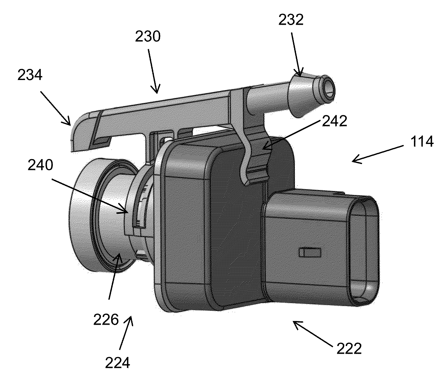
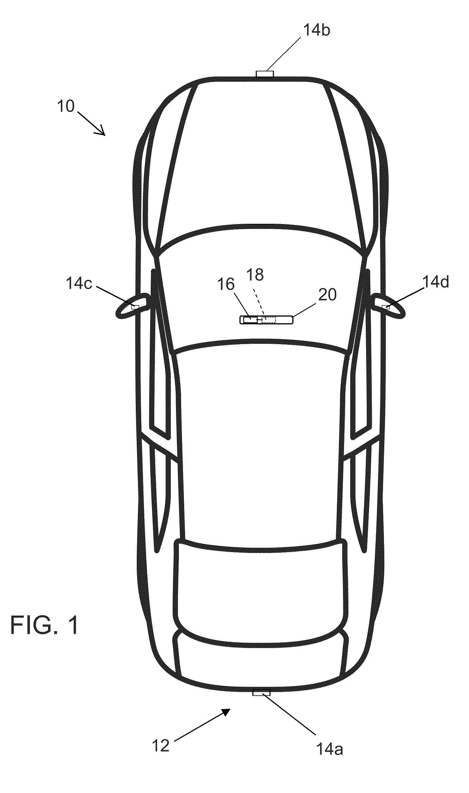
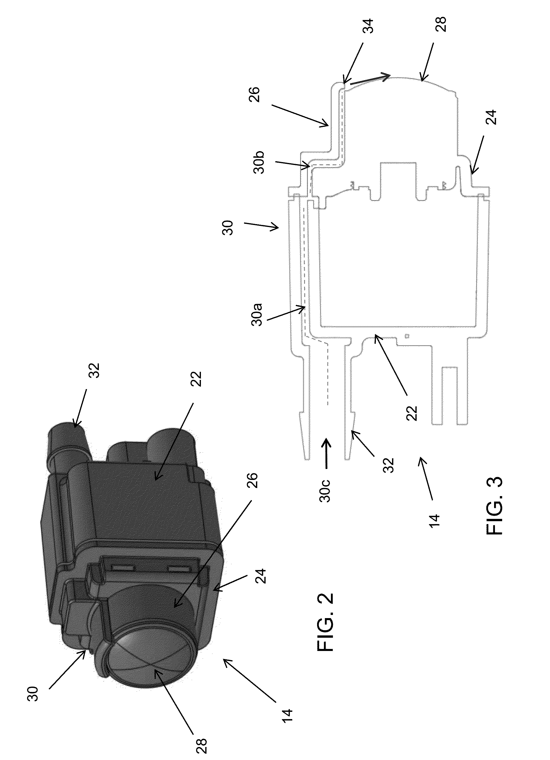
[0007]The present invention provides a vision system or imaging system for a vehicle that utilizes one or more cameras (preferably one or more CMOS cameras) to capture image data representative of images exterior of the vehicle, and provides a lens washer integrated into the camera housing to provide pressurized fluid at the camera lens. The camera may be mounted or disposed at an exterior structure of the vehicle, such as, for example, a vehicle panel, grill, bumper, fascia, light bar, center high mounted stop lamp (CHMSL) or the like, with its lens viewing exterior of the vehicle. The lens washer may be molded with the housing portion and lens barrel of the camera and provides a fluid passageway along the housing and lens barrel and a nozzle that sprays pressurized fluid onto the lens to remove dirt or debris from the lens. Optionally, the lens washer may comprise a separate element that snap attaches at the lens barrel and / or at the camera housing such that, when snap attached, the nozzle end is directed at the outer surface of the lens of the camera.

Problems solved by technology

Obscuring view by mud, salt or dust is becoming an increasing issue for vehicle cameras as their ability to determine and recognize objects can be limited or interrupted.
Both systems are aids that have to be installed in addition to the camera, thereby adding cost to the assembly process at the system suppliers.
Both systems take up packaging room, thus reducing the available area of engine air flow through the front grille (for a forward viewing camera).
Both systems are seen as an interference to the overall scheme of the vehicle by studio designers.

Method used


Image

  • Vehicle camera with lens washer system
  • Vehicle camera with lens washer system
  • Vehicle camera with lens washer system

Examples


Embodiment Construction

[0025]A vehicle vision system and / or driver assist system and / or object detection system and / or alert system operates to capture images exterior of the vehicle and may process the captured image data to display images and to detect objects at or near the vehicle and in the predicted path of the vehicle, such as to assist a driver of the vehicle in maneuvering the vehicle in a rearward direction. The vision system includes an image processor or image processing system that is operable to receive image data from one or more cameras and provide an output to a display device for displaying images representative of the captured image data. Optionally, the vision system may provide a top down or bird's eye or surround view display and may provide a displayed image that is representative of the subject vehicle, and optionally with the displayed image being customized to at least partially correspond to the actual subject vehicle.

[0026]Referring now to the drawings and the illustrative embo...


PUM


Abstract

A vision system of a vehicle includes a camera configured to be disposed at an exterior portion of a vehicle so as to have a field of view exterior of the vehicle. The camera includes a lens. A washer includes a connector and fluid passageway. The washer is configured to be detachably attached at the camera when the camera is disposed at the exterior portion of the vehicle. When attached at the camera, the connector is configured for connection to a washer system of a vehicle such that, when the vehicle washer system is actuated, pressurized fluid flows through the fluid passageway and onto the lens.

Description

CROSS REFERENCE TO RELATED APPLICATIONS[0001]The present application claims the filing benefits of U.S. provisional applications, Ser. No. 62 / 189,963, filed Jul. 8, 2015; Ser. No. 62 / 158,838, filed May 8, 2015 and Ser. No. 62 / 134,062, filed Mar. 17, 2015, which are hereby incorporated herein by reference in their entireties.FIELD OF THE INVENTION[0002]The present invention relates generally to a vehicle vision system for a vehicle and, more particularly, to a vehicle vision system that utilizes one or more cameras at a vehicle.BACKGROUND OF THE INVENTION[0003]Use of imaging sensors in vehicle imaging systems is common and known. Examples of such known systems are described in U.S. Pat. Nos. 5,949,331; 5,670,935 and / or 5,550,677, which are hereby incorporated herein by reference in their entireties.[0004]Obscuring view by mud, salt or dust is becoming an increasing issue for vehicle cameras as their ability to determine and recognize objects can be limited or interrupted. Vehicle man...

Claims


Application Information

Patent Timeline
Patent Type & Authority Applications(United States)
IPC IPC(8): B60S1/56H04N5/225H04N5/217G02B27/00B60R11/04B60S1/48
CPCB60S1/56B60R11/04B60S1/48B60R2011/004G02B27/0006H04N5/2252H04N5/2171B60S1/52H04N23/811H04N23/57
Inventor DREIOCKER, RENEMLECZKO, JAMIE A.BYRNE, STEVEN V.LU, YUESHENGCONGER, JONATHAN D.
Owner MAGNA ELECTRONICS
Why Eureka
Try Eureka