
Water environment mobile robots

a robot and water environment technology, applied in underwater equipment, special-purpose vessels, instruments, etc., can solve the problems of difficult inspection of infrastructure located in shallow water, high cost, and difficulty in using divers,

Inactive Publication Date: 2016-09-22
SAUDI ARABIAN OIL CO
View PDF13 Cites 45 Cited by
  • Summary
  • Abstract
  • Description
  • Claims
  • Application Information

AI Technical Summary

Benefits of technology

The present invention is a water environment robotic system that includes an underwater robotic vehicle and a water-surface robotic vehicle that communicate with each other through the water. The system includes an alignment control system that helps maintain the relative positions of the two vehicles. The water-surface robotic vehicle can move along the surface of the water and can also be tethered to the underwater robotic vehicle. The system also includes various sensors and inspection devices for underwater and marine life cleaning. The technical effects of the invention include improved communication between the two vehicles, better alignment control, and more efficient and effective inspection and cleaning of the water environment.

Problems solved by technology

However, using divers raises safety concerns and is expensive.
Accordingly, it is difficult to inspect infrastructure located in shallow water, areas close to the shore, and other hazardous areas because of the limitation of the support boat.
Shallow waters introduce a big challenge in terms of accessibility as large ships, to which big working-class ROVs are tethered, cannot navigate these areas in fear of colliding with the seafloor.
Therefore, small zodiacs (rubber boats) are used to access these areas but can only be used to deploy small observation-class ROVs.
These ROVs are good enough for visual inspection but are not suitable for taking UT and CP measurements since subsea currents would move them around and prevent them from taking stable readings off the pipeline.
Using divers for these tasks is extremely slow and inefficient due to the logistics related to navigating the boats in shallow waters.
The process is slow and the average inspection speed is around 0.5 Km / day of underwater pipelines.
While underwater mobile robots provide inspection capability, if the support boat is located at large distances from the underwater mobile robot the robots cannot be effectively controlled and / or data cannot be effectively received from the robot because of the difficulties and limitations associated with underwater communication over long distances.

Method used


Image

  • Water environment mobile robots
  • Water environment mobile robots
  • Water environment mobile robots

Examples


Embodiment Construction

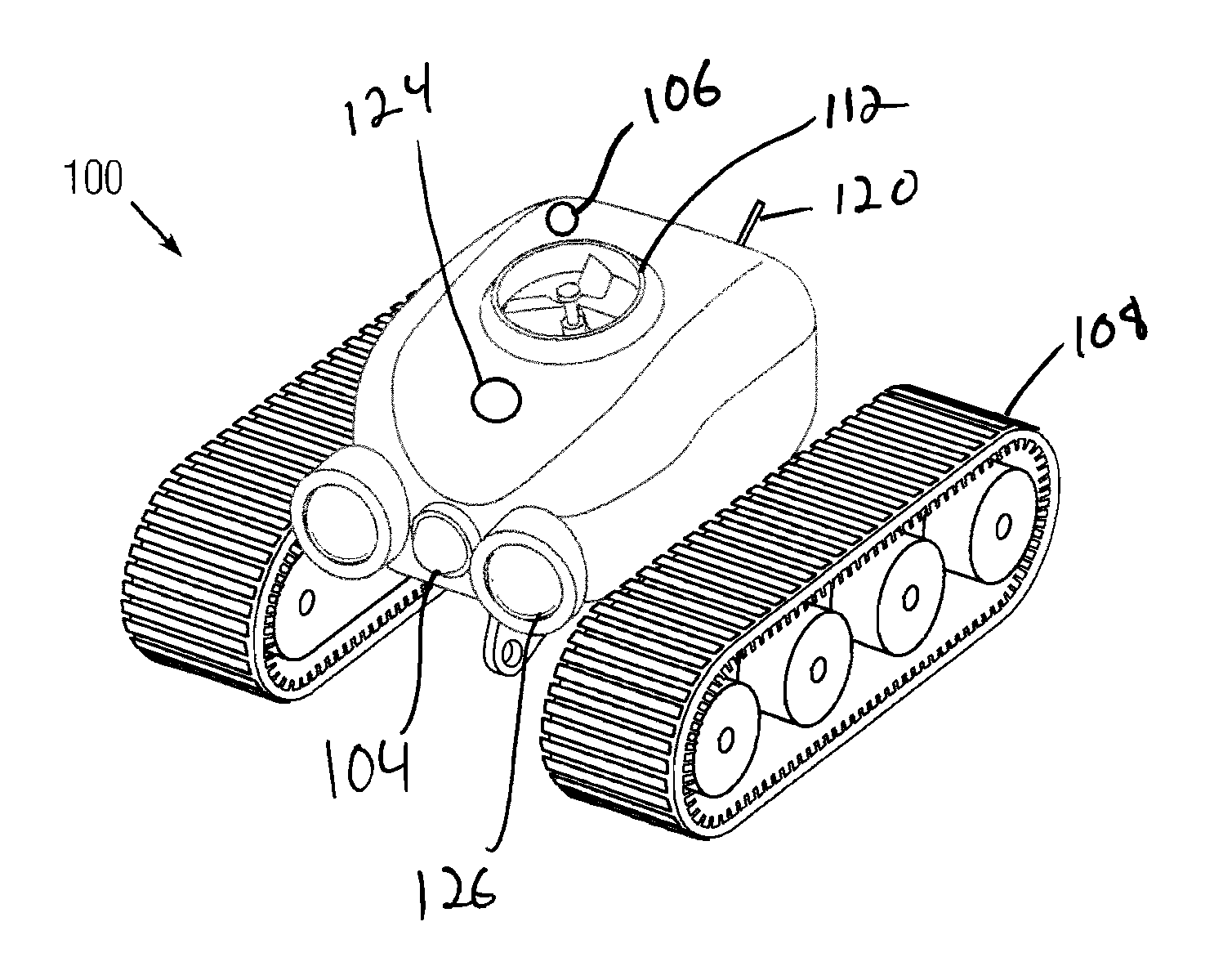
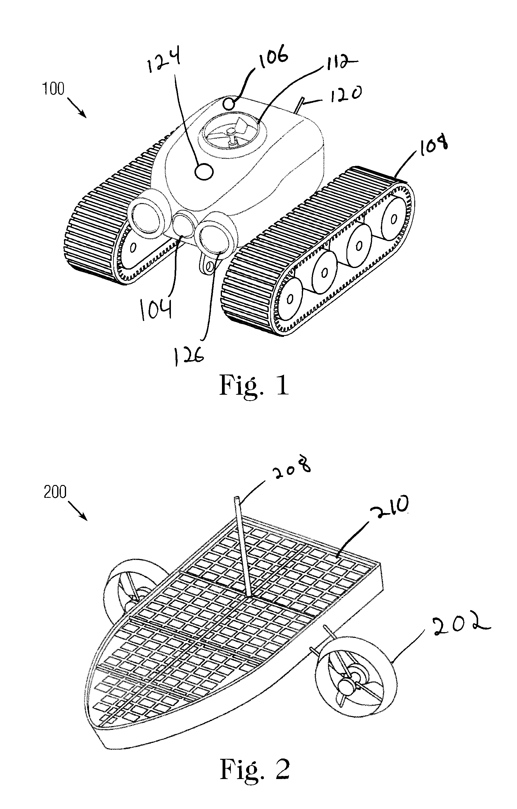
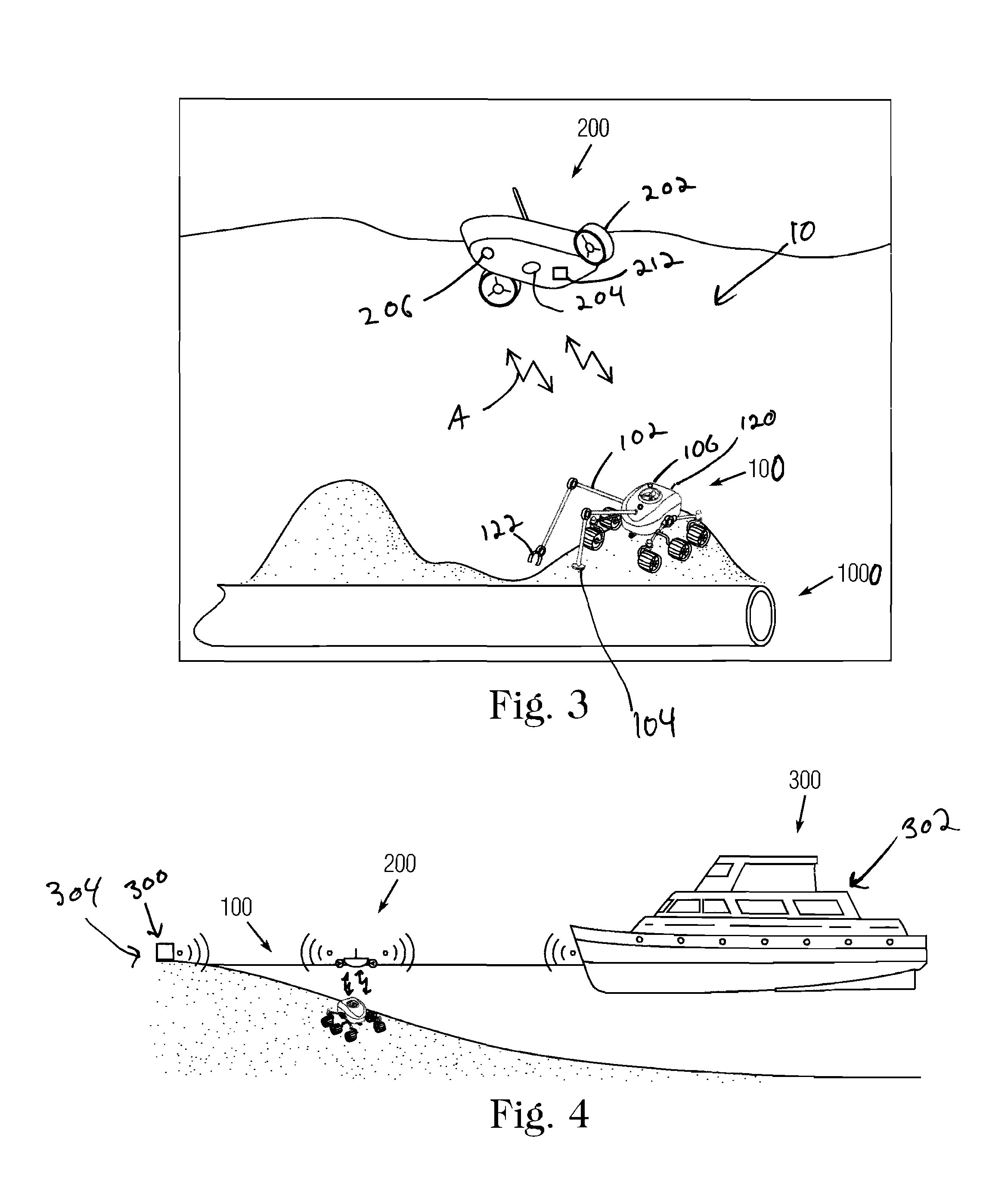
[0034]Referring to FIGS. 1-3, an aquatic environment robotic system 10 includes an underwater robot 100 and a surface robot 200. The underwater robot 100 is structured so that it can dive under the surface of the water and perform various maintenance and inspection operations on underwater infrastructure. The surface robot 200 remains on the surface of the water and has its own propulsion system 202 so that it can move along the surface of the water in order to maintain close proximity to the underwater robot 100. As the underwater robot 100 moves underwater the surface robot 200 moves in a corresponding fashion in order to maintain proximity with the underwater robot. Since the surface robot 200 moves to stay in close proximity to the underwater robot 100, the distance between the two robots is maintained at a minimum. Accordingly, the communication distance through the water between the surface robot 200 and the underwater robot 100 is minimized. Minimizing the communication dista...


PUM


Abstract

A water environment robotic system that includes a control station, an underwater robotic vehicle, and a water-surface robotic vehicle. The underwater robotic vehicle is in communication with the water-surface robotic vehicle and the water-surface robotic vehicle is in communication with the control station. Accordingly, the water-surface robotic vehicle can act as a relay between the control station and the underwater robotic vehicle. The water-surface robotic vehicle is further capable of detecting the position of the underwater vehicle and automatically adjusting the position of the underwater vehicle in order to maintain general vertical alignment between the two vehicles.

Description

CROSS-REFERENCE TO RELATED APPLICATIONS[0001]This application is based on and claims priority to U.S. Provisional Patent Application Ser. No. 62 / 133,863, filed on Mar. 16, 2015, which is hereby incorporated by reference as if set forth in its entirety herein.FIELD OF THE INVENTION[0002]A system, method, and devices for performing inspection of underwater assets including underwater pipelines and structures are provided that includes an underwater robot and a surface robot.BACKGROUND OF THE INVENTION[0003]Mobile robots can play an integral role in the inspection of industrial infrastructure, including infrastructure located under water and in marine environments. Conventionally, in order to inspect the underwater infrastructure (e.g., under water pipelines), either human divers or remotely operated vehicles are used. However, using divers raises safety concerns and is expensive. Remotely operated vehicles eliminate many of the safety concerns associated by divers, but these vehicles ...

Claims


Application Information

Patent Timeline
Patent Type & Authority Applications(United States)
IPC IPC(8): B63G8/00B60F3/00B63G8/38B63G8/14B63G8/39
CPCB63G8/001B63G8/14B63G8/39B63G2008/007B60F3/0061B60F3/0015B63G8/38G05D1/0022B63G2008/002B63G2008/005B63G2008/008H04B7/14H04B13/02G05D1/0692G05D1/0011G05D1/10
Inventor OUTA,, ALILATIF, FADL ABDELPATEL, SAHEJADTRIGUI, HASSANEAMER, AYMAN MOHAMMADOBEDAN, AMEEN AL
Owner SAUDI ARABIAN OIL CO
Learn More