Conductive sheet, capacitive touch panel, and display device

a capacitive touch panel and display device technology, applied in the field of conductive sheets and capacitive touch panels, can solve the problems of degrading light transmission and electrodes not functioning, and achieve the effect of greatly reducing the amount of capacitance change between before and after the pressing (touching) of the finger, and increasing the change of capacitan

Active Publication Date: 2016-09-22
FUJIFILM CORP
View PDF3 Cites 21 Cited by
  • Summary
  • Abstract
  • Description
  • Claims
  • Application Information

AI Technical Summary

Benefits of technology

[0074]FIG. 7 illustrates when the average cell pitch Ps of the second cells 22B is two times the average cell pitch Pd of the first cells 22A.
[0075]That is, when the average cell pitch Pd of the first cells 22A is 100 μm, the average cell pitch Ps of the second cells 22B is set to one of 200 μm, 300 μm, 400 μm, 500 μm, 600 μm, 700 μm, and 800 μm. When the average cell pitch Pd of the first cells 22A is 250 μm, the average cell pitch Ps of the second cells 22B is set to one of 500 μm, 750 μm, 1,000 μm, 1,250 μm, 1,500 μm, 1,750 μm, and 2,000 μm.
[0076]In this way, the average cell pitch Ps is set to an integer multiple of the average cell pitch Pd, whereby interference between the first cells 22A and the second cells 22B is reduced. For this reason, moire is greatly reduced compared to when Ps / Pd has a value (for example, 1.5, 2.3, or the like) other than an integer.
[0077]In addition, when Ps / Pd is in a range of 2 to 8, the amount of change in capacitance between before and after the press (touch) of the finger is increased compared to a case where Ps / Pd is 1, in other words, a case where the average cell pitch Pd of the first cells 22A and the average cell pitch Ps of the second cells 22B are equal to each other. This will be described below.
[0078]The second cells 22B are not limited to the shape illustrated in FIG. 6, and may of course have a horizontally long diamond shape or a vertically long diamond shape.
[0079]As shown in FIG. 2, one end portion of each second electrode 18B is electrically connected to a second terminal wiring pattern 42b of the thin wire 20B through a second connection portion 40b.

Problems solved by technology

However, in this case, light transmission is degraded when the opening area of the cell becomes small.
When this happens, there is a problem in that the electrodes do not function when unintended disconnection of the electrodes occurs.
Accordingly, as described in JP2012-243058A, while increasing the cell pitch of the upper electrode to increase detection sensitivity has been considered, it is understood that there is a severe problem in that the difference in the cell pitch between the upper electrode and the lower electrode causes periodic interference (moire) between the two electrodes and the existence of the mesh is easily visually recognizable.

Method used


Image

  • Conductive sheet, capacitive touch panel, and display device
  • Conductive sheet, capacitive touch panel, and display device
  • Conductive sheet, capacitive touch panel, and display device

Examples


example 1

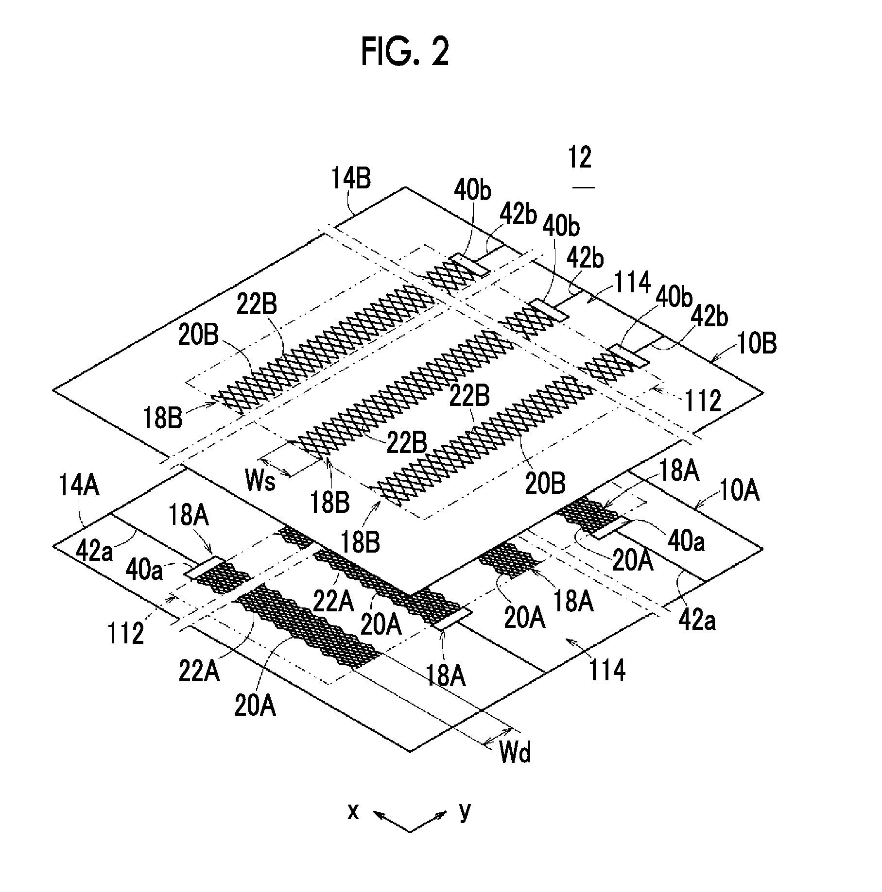
[0118]A conductive sheet in which one lower electrode (first electrode 18A) having an electrode width Wd of 5 mm and an average cell pitch Pd of 300 μm is formed on a transparent base and a conductive sheet in which one upper electrode (second electrode 18B) having an electrode width Ws of 5 mm is formed on a transparent base are bonded to each other through an OCA to obtain electrode laminate. Of course, the lower electrode and the upper electrode are partially opposed to each other.

[0119]In this configuration, the average cell pitch Ps of the upper electrode is varied as shown in Table 1 described below, and electrode laminates of Examples 1 to 5 and Comparative Examples 1 to 3 are constituted. Thereafter, the amount (ΔCm value) of change in capacitance between before and after touch in each electrode laminate is determined. When the value of ΔCm is large, the possibility of detecting touch is increased, and detection accuracy is improved.

TABLE 1Electrode AverageCell Pitch (μm)Low...


PUM


Abstract

In a conductive sheet constituting a touch panel for use in a display device, it is possible to improve the transmittance of electrodes having meshes, to improve sensitivity of touch detection, and to suppress the occurrence of moire. A conductive sheet has an underlying first electrode and an overlying second electrode with a second sheet body as an insulating layer sandwiched therebetween. The first electrode and the second electrode respectively include a plurality of first cells and a plurality of second cells which are formed in a diamond shape by making thin wires and formed with metal wires intersect each other. The average cell pitch of the second cells is set to an integer multiple equal to or greater than two times and equal to or less than eight times the average cell pitch of the first cell.

Description

CROSS-REFERENCE TO RELATED APPLICATIONS[0001]This application is a Continuation of PCT International Application No. PCT / JP2014 / 074912 filed on Sep. 19, 2014, which claims priority under 35 U.S.C §119(a) to Japanese Patent Application No. 2013-250333 filed Dec. 3, 2013. Each of the above applications is hereby expressly incorporated by reference, in its entirety, into the present application.BACKGROUND OF THE INVENTION[0002]1. Field of the Invention[0003]The present invention relates to a conductive sheet, a capacitive touch panel, and a display device.[0004]2. Description of the Related Art[0005]As a display device of a multifunctional mobile phone (smartphone), a digital camera, or the like, a so-called touch panel on which various operations can be performed by touch with a finger has been widely used. In these devices, the display device has a small size, and recently, a touch panel has also been used in a large display device of a personal computer or the like. In particular, a...

Claims


Application Information

Patent Timeline
Patent Type & Authority Applications(United States)
IPC IPC(8): G06F3/044
CPCG06F3/044G06F3/0412G06F2203/04112G06F3/0445G06F3/0446
Inventor SATOU, TASUKU
Owner FUJIFILM CORP
Why Eureka
Try Eureka