

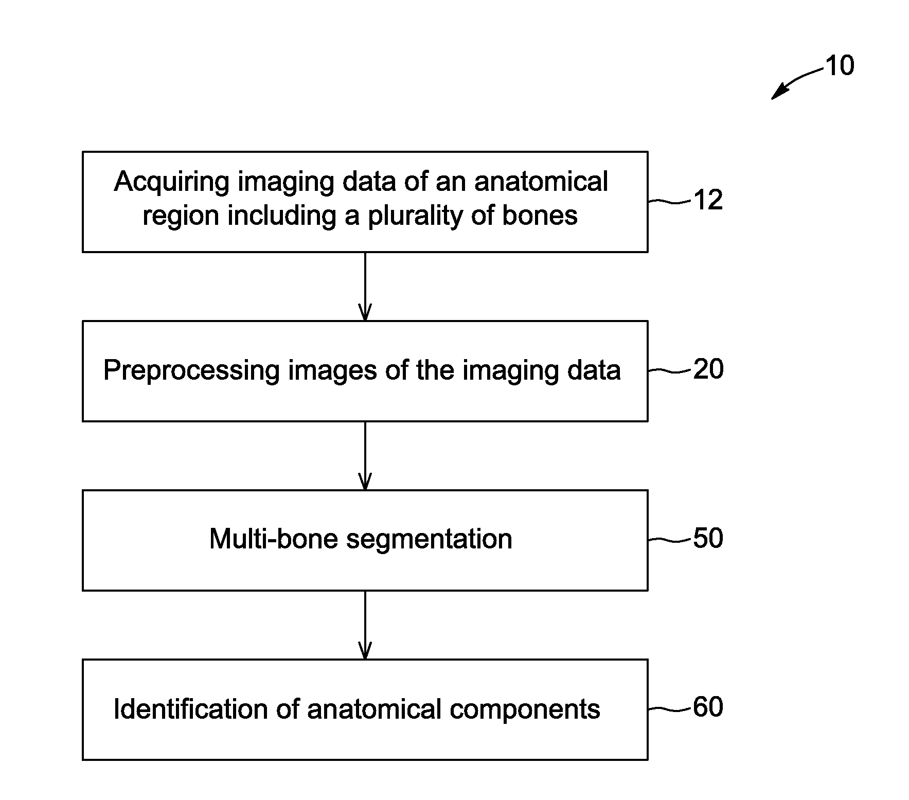
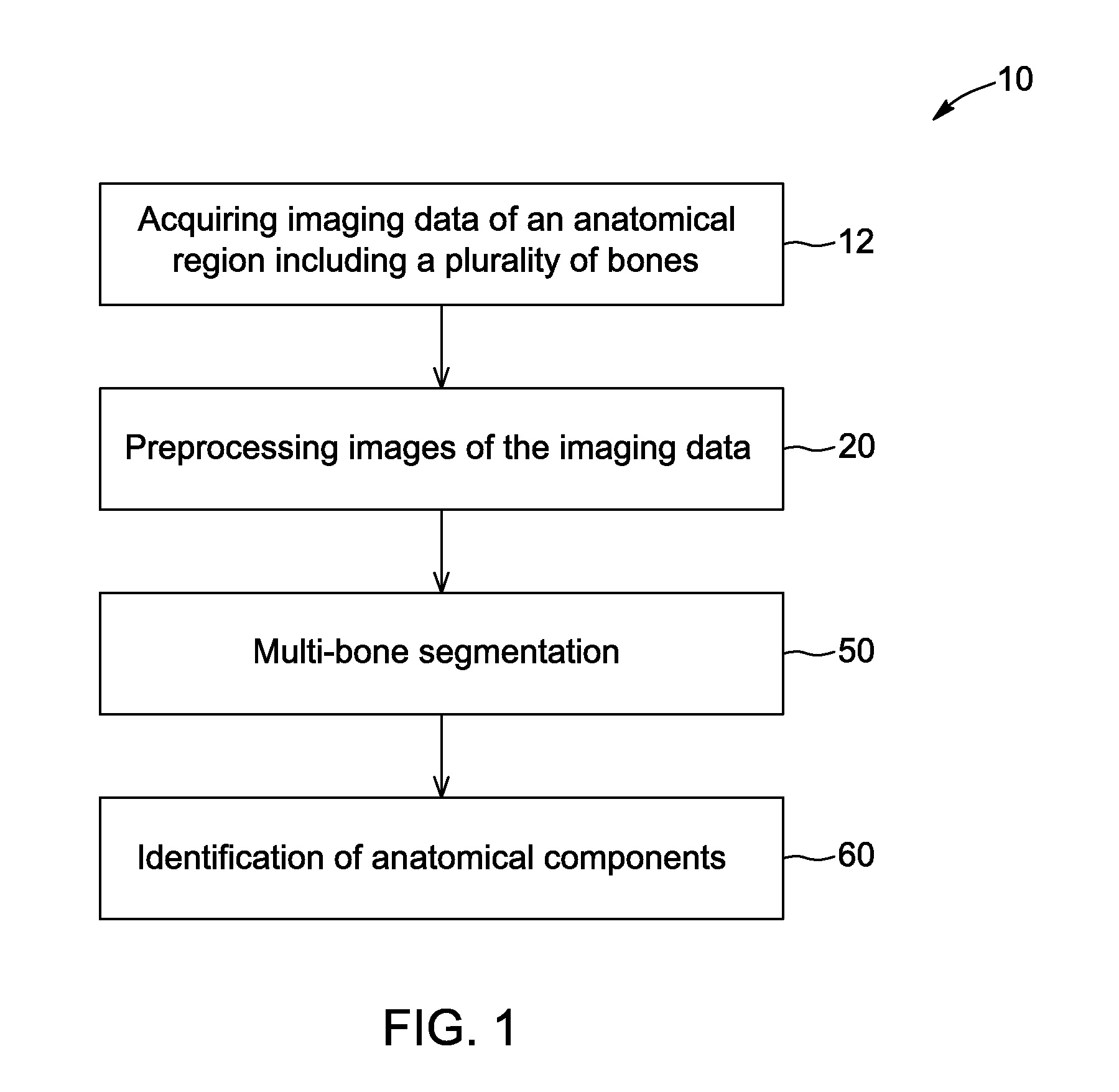
Method and system for performing multi-bone segmentation in imaging data
a multi-bone segmentation and imaging data technology, applied in image enhancement, instruments, applications, etc., can solve the problems of lowering the contrast of the boundaries of neighboring bones with respect to background, and failing to segment images using well-known imaging techniques
- Summary
- Abstract
- Description
- Claims
- Application Information
AI Technical Summary
Benefits of technology
Problems solved by technology
Method used
Image

Examples
Embodiment Construction
[0302]In the following description, the same numerical references refer to similar elements. The embodiments mentioned in the present description are embodiments only, given solely for exemplification purposes.
[0303]Moreover, although the embodiments of the method and system for performing multi-bone segmentation consist of certain configurations as explained and illustrated herein, not all of these configurations are essential and thus should not be taken in their restrictive sense. It is to be understood, as also apparent to a person skilled in the art, that other suitable components and cooperation thereinbetween, as well as other suitable configurations, may be used for the method and system for performing multi-bone segmentation, as will be briefly explained herein and as can be easily inferred herefrom by a person skilled in the art.
[0304]As mentioned above, segmentation of bones from 3D images is important to many clinical applications such as visualization, enhancement, dise...
PUM
 Abstract
Description
Claims
Application Information