
Automatic frying machine

a technology frying pan, which is applied in the field of automatic frying machine, can solve the problems of increasing product cost, increasing labor charge, and reducing productivity, and achieves the effects of reducing heat influence, efficient cooking, and minimizing a

Inactive Publication Date: 2016-09-29
KORNIC AUTOMATION
View PDF3 Cites 6 Cited by
  • Summary
  • Abstract
  • Description
  • Claims
  • Application Information

AI Technical Summary

Benefits of technology

The automatic frying machine described in this patent can cook fried food like chicken or potato, and it can do so automatically. It has a single button to activate the machine and can cook a variety of fried foods. The machine is designed to minimize the impact of heat and to efficiently cook food by using one common transfer unit and minimizing the impact between different functions.

Problems solved by technology

This lowers productivity, raises labor charge due to the increase of the number of workers and increases the product cost, thereby decreasing the added value of the product.
This has a low productivity since it takes time to finish frying.
Also, in the frying machine of the prior art, an input of a plurality of materials into one frying machine simultaneously to increase the efficiency of cooking causes the materials to be stuck together, thereby resulting a poor quality of the fried food having un-fried parts and over-fried parts.

Method used


Image

  • Automatic frying machine
  • Automatic frying machine
  • Automatic frying machine

Examples


first embodiment

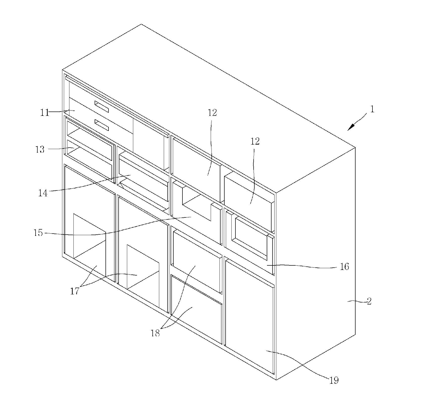
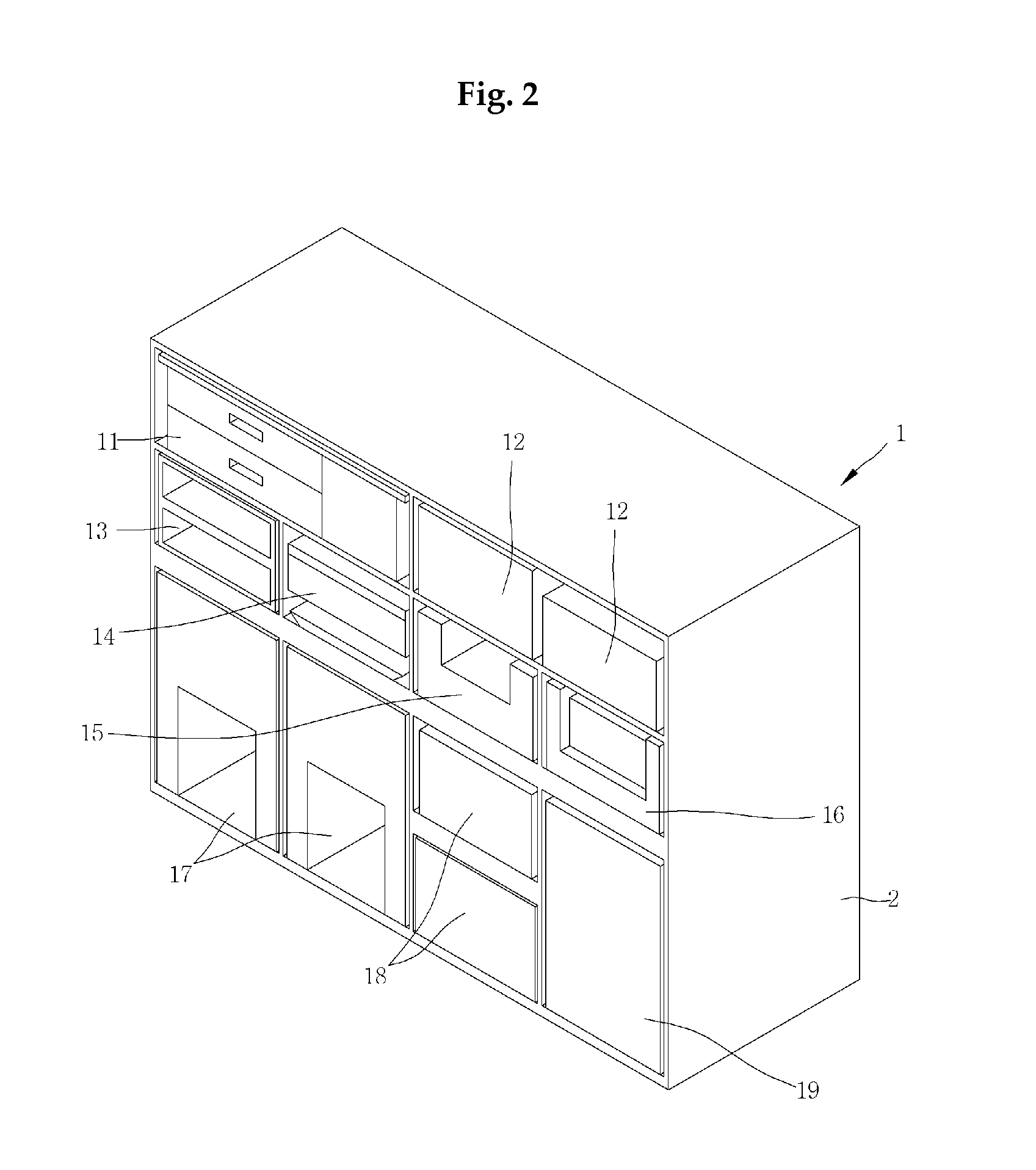
[0035]FIGS. 2 to 6 represent the automatic frying machine according to the first embodiment according to the present invention. As shown in FIGS. 2 to 6, the automatic frying machine 1 comprises a frying process part 10 which performs frying process and a transfer part 20 which transfers frying materials.

[0036]The frying process 10 is arranged on the front part of the automatic frying machine 1 and it has a plurality of module-type process units which perform predetermined frying processes, respectively.

[0037]The automatic frying machine 1 has a body frame 2 which is provided with horizontal partitions 2a and vertical partitions 2b, respectively. The plurality of process units 11 to 19 are detachably arranged in spaces which are separated from each other by means of the horizontal partitions 2a and the vertical partitions 2b.

[0038]Further, a front-rear partition 2c is provided between the transfer part and each space divided by the horizontal partitions 2a and the vertical partitio...

second embodiment

[0072]FIGS. 7 and 8 represent the second embodiment of the present invention. This embodiment is the same as the first embodiment except the transfer unit. The same reference numerals are used to indicate the same elements and the repeated explanations will be omitted.

[0073]As shown in FIGS. 7 and 8, the transfer unit according to this embodiment comprises a plurality of baskets 40a, 40b, a plurality of horizontal moving units 60 and an elevation unit 51.

[0074]The plurality of basket 40a, 40b are engaged with each horizontal moving unit 60 by a robot hand 60a, 60b to move forward and backward and to take frying material in and out through an opening formed on the plurality of process units.

[0075]The horizontal moving unit 60 is configured such that a plurality of horizontal moving units are engaged with the elevation moving units 51 to move upward and downward.

[0076]The horizontal moving unit 60 is configured as a screw bar having threads on the outer surface such that the basket 40...


PUM


Abstract

The present invention relates to an automatic frying machine comprising: a frying process part having divided spaces, wherein a plurality of module-type process units which carry out each of predetermined frying processes are detachably disposed in the divided spaces; and a transfer part which is in communication with the plurality of process units of the frying process part and which carries a basket having frying materials in and out of the plurality of process units and moves the basket, wherein the transfer part comprises: a basket which carries the frying material in and out through an opening formed on the plurality of process units; a transfer unit which raises and lowers the basket and slides it back and forth; and a horizontal moving part which moves the transfer unit horizontally.

Description

CROSS REFERENCE TO RELATED APPLICATIONS[0001]This application claims priority to Korean Patent Application No. 10-2015-0039921, filed on Mar. 23, 2015, and the entire disclosures of these applications are incorporated herein by reference for all purposes.TECHNICAL FIELD[0002]The present invention relates to an automatic frying machine, and in particular to an automatic frying machine which cooks fried food such as a fried chicken or a fried potato and which performs automatically cooking process from the insertion of material to the completion of cooking by the actuation of one button.BACKGROUND ART[0003]In general, fried food is popular because it is crispy and has aromatic flavor unique to fat. For example, there are oil fried chicken oil, seasoned fried chicken which is made by applying seasoning sauce to fried chicken, fried potato, etc.[0004]Conventionally, for the cooking process, materials are mixed manually and batter is spread on the materials. After that materials are put ...

Claims


Application Information

Patent Timeline
Patent Type & Authority Applications(United States)
IPC IPC(8): A47J37/12
CPCA47J37/1276A47J37/1219A47J37/1228
Inventor KIM, KYEUNG-TAIKIM, HYUN-TAE
Owner KORNIC AUTOMATION
Learn More