Vehicle seat air-conditioning device

a vehicle seat and air-conditioning technology, which is applied in the direction of vehicle heating/cooling devices, seat heating/ventilation devices, vehicle arrangements, etc., can solve the problems of extremely small space formed around the rear foot duct under the seat, and components of the vehicle seat air-conditioning devices including the blower are hardly disposed under

Inactive Publication Date: 2016-09-29
DENSO CORP
View PDF7 Cites 13 Cited by
  • Summary
  • Abstract
  • Description
  • Claims
  • Application Information

AI Technical Summary

Benefits of technology

[0009]According to the vehicle seat air-conditioning device, since the branch duct is branched laterally from the ventilation duct, and the blower is arranged on the lateral side of the ventilation duct in the vehicle on the condition of being mounted in the vehicle, the blower can be located at

Problems solved by technology

Especially in an upper-lower direction of a vehicle, a space formed around a rear-foot duct under the seat is extremely small.
Accordingly, components

Method used


Image

  • Vehicle seat air-conditioning device
  • Vehicle seat air-conditioning device
  • Vehicle seat air-conditioning device

Examples


first embodiment

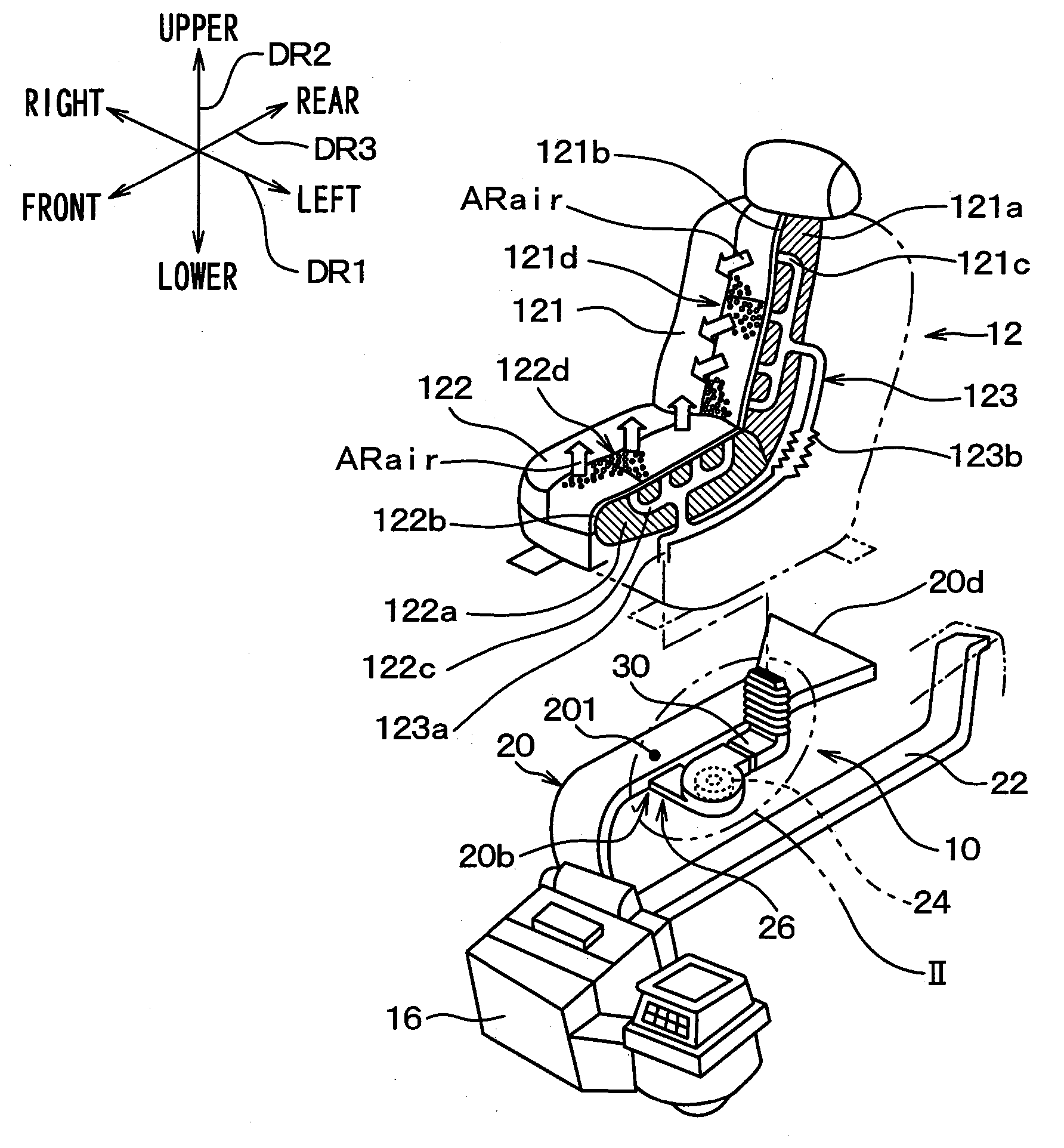
[0019]FIG. 1 is an exploded perspective view illustrating a vehicle seat air-conditioning device 10 and a vehicle seat 12 to which conditioned air is delivered from the vehicle seat air-conditioning device 10 according to a first embodiment. In FIG. 1, an arrow DR1 shows a left-right direction of a vehicle (i.e., a width direction of the vehicle), an arrow DR2 shows an upper-lower direction of the vehicle, and an arrow DR3 shows a front-rear direction of the vehicle. The left-right direction shown by the arrow DR1 is a direction on a basis of a front in a traveling direction of the vehicle, and an actual left-right direction shown in, for example, FIGS. 3, 4 may be reversed. In FIG. 1, a sectional view of the vehicle seat 12 is illustrated.

[0020]The vehicle seat 12 shown in FIG. 1 is a front seat that is arranged on a front side of a rear seat that is not shown. The vehicle seat 12 is a blowing target seat that is a target to which conditioned air is blown from the vehicle seat air-...

second embodiment

[0050]A second embodiment of the present disclosure will be described. In the present embodiment, features that are different from the first embodiment will be described mainly.

[0051]The seat air-conditioning device 10 of the present embodiment is different from that of the first embodiment and can deliver air inside of the vehicle compartment, not only the conditioned air from the air conditioning unit 16, to the vehicle seat 12 without passing through the air conditioning unit 16. FIG. 4 is a perspective view illustrating a part of the seat air-conditioning device 10 of the present embodiment.

[0052]As shown in FIG. 4, the seat air-conditioning device 10 has a communication duct 38 and an introducing air switching mechanism 40 on a suction side of the blower 24. The communication duct 38 is a duct protrudes laterally from the branch duct 26, specifically to a rear side of the vehicle. The communication duct 38 is made of, for example, resin, and formed integrally with the branch du...

third embodiment

[0060]A third embodiment of the present disclosure will be described. In the present embodiment, features that are different from the first embodiment will be described mainly.

[0061]As shown in FIG. 5, the vehicle seat 12 has a seat connector 124 at each of four corners of the vehicle seat 12 on a lower side of the vehicle seat 12 to connect the vehicle seat 12 to the floor 18 of the vehicle compartment. That is, the vehicle seat 12 has four seat connectors 124. The seat connectors 124 are configured by a metal plate molded by a method such as pressing and are respectively fastened to four seat fixing parts 181 that are disposed on the floor 18 of the vehicle compartment.

[0062]FIG. 6 is a side view illustrating the vehicle seat 12 when viewed from a left side of the vehicle as shown by an arrow VI in FIG. 5. As shown in FIG. 6, the vehicle seat 12 has a seat rail 126 that enables a seat body 125 including the back portion 121 and the seat cushion 122 to move in the front-rear direct...


PUM


Abstract

A vehicle seat air-conditioning device has a branch duct and a blower. The branch duct is branched laterally from a ventilation duct on a condition of being mounted in a vehicle. The ventilation duct delivers air, which is blown from an air conditioning unit that air-conditions an inside of a vehicle compartment, to a periphery of a rear seat. The blower draws air from the branch duct and blows the air into a ventilation path formed in a blowing target seat. The blow is arranged on a lateral side of the ventilation duct on the condition of being mounted in the vehicle. Since the blower is arranged on the lateral side of the ventilation duct in the vehicle, the blower can be located at a lower position regardless of a length of the ventilation duct in an upper-lower direction. Therefore, a space in the vehicle that is occupied in the upper-lower direction by the ventilation duct and the blower as a whole can be reduced.

Description

CROSS REFERENCE TO RELATED APPLICATION[0001]This application is based on Japanese Patent Application No. 2013-228878 filed on Nov. 4, 2013, the disclosure of which is incorporated herein by reference.TECHNICAL FIELD[0002]The present disclosure relates to a vehicle seat air-conditioning device blowing conditioned air in a vehicle seat.BACKGROUND ART[0003]Various vehicle seat air-conditioning devices that uses conditioned air of which temperature is adjusted by an air conditioning unit that air-conditions an inside of a vehicle compartment have been provided conventionally. For example, a vehicle seat air-conditioning device of Patent Literature 1 uses a rear-foot duct that delivers conditioned air from an air conditioning unit to a rear seat, and takes in the conditioned air from the rear-foot duct. According to Patent Literature 1, a cost can be reduced by omitting a dedicated duct.[0004]The vehicle seat air-conditioning device of Patent Literature 1 further has a blower that blows ...

Claims


Application Information

Patent Timeline
IPC IPC(8): B60H1/00B60N2/56B60H1/24
CPCB60H1/00285B60H1/00564B60N2/5657B60H1/00521B60N2/5628B60H1/244B60H2001/003
Inventor TANAKA, YUUSUKENIIMI, YASUHIKOFUJII, TAKAHISA
Owner DENSO CORP
Why Eureka
Try Eureka