Placement structure for peripheral information detecting sensor, and self-driving vehicle
a technology of peripheral information and positioning structure, which is applied in vehicle position/course/altitude control, using reradiation, instruments, etc., can solve the problems of deteriorating detection accuracy of peripheral information detecting sensor, difficult to ensure the mounting rigidity of the sensor, and mar the exterior appearance of the vehicle, so as to achieve excellent effect, excellent effect, and design the effect of the vehicl
- Summary
- Abstract
- Description
- Claims
- Application Information
AI Technical Summary
Benefits of technology
Problems solved by technology
Method used
Image
Examples
first embodiment
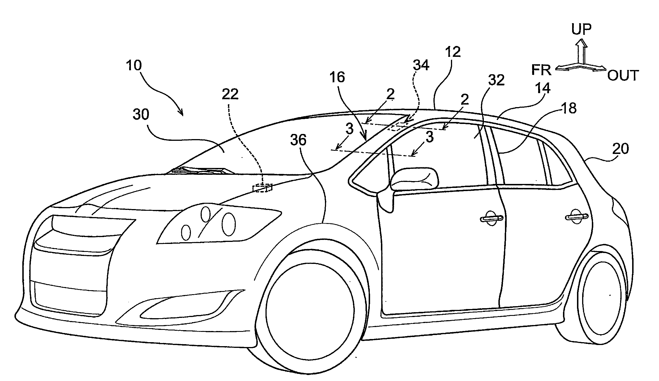
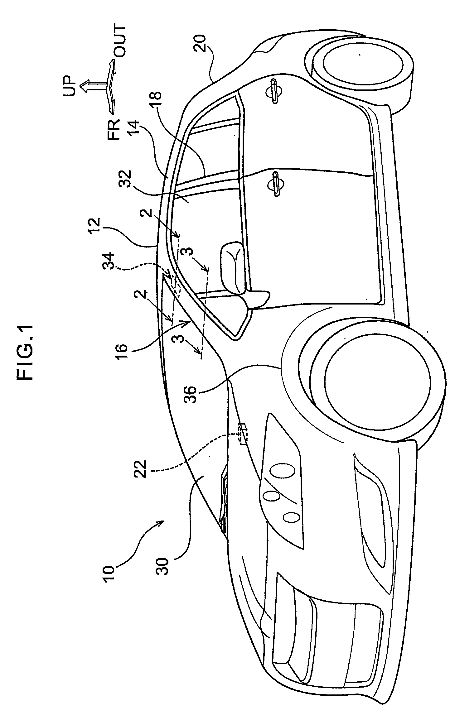
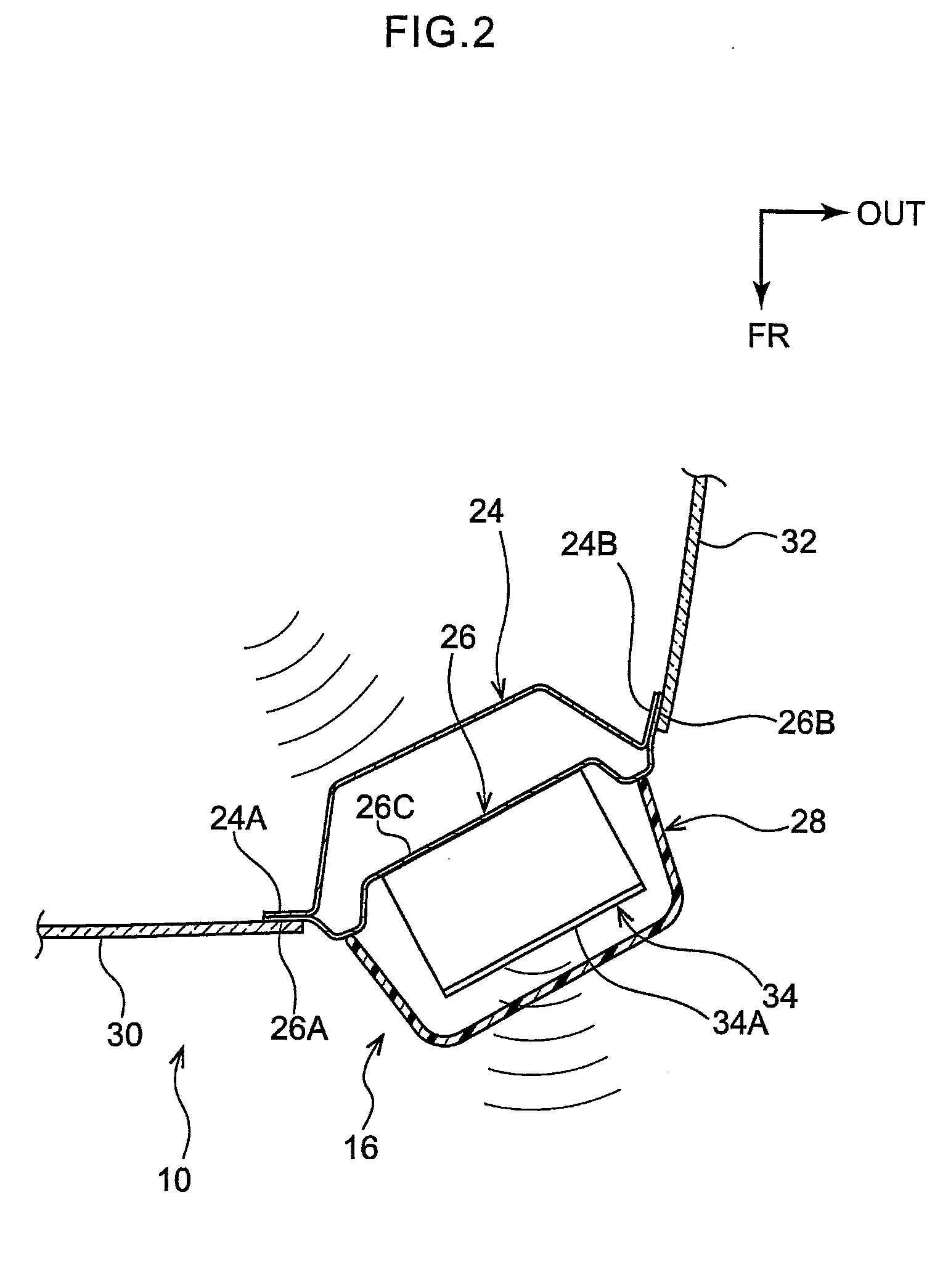
[0051]A self-driving vehicle, to which is applied a placement structure for a peripheral information detecting sensor relating to a first embodiment, is described hereinafter with reference to FIG. 1 through FIG. 3. Note that arrow FR that is shown appropriately in FIG. 1 indicates the vehicle front side of a self-driving vehicle at which the peripheral information detecting sensor is installed, arrow UP indicates the vehicle upper side, and arrow OUT indicates the vehicle transverse direction outer side. Further, in the following description, when longitudinal, vertical and left-right directions are used without being specified, they respectively mean the vehicle longitudinal direction, the vehicle vertical direction, and the left and right directions when facing in the advancing (forward-moving) direction.
[0052]As shown in FIG. 1, a roof panel 12 is disposed at the vehicle upper portion of a self-driving vehicle 10 (hereinafter simply called “vehicle 10”). Further, a pair of left ...
second embodiment
[0074]A self-driving vehicle, to which is applied a placement structure for a peripheral information detecting sensor relating to a second embodiment, is described next with reference to FIG. 4. Note that structures that are similar to those of the first embodiment are denoted by the same reference numerals, and description thereof is omitted.
[0075]As shown in FIG. 4, a peripheral information detecting sensor 41 relating to the present embodiment is disposed at the upper portion of the front pillar 16 of a self-driving vehicle 40 (hereinafter simply called “vehicle 40”). Concretely, the peripheral information detecting sensor 41 is disposed at the vehicle outer side of the front pillar 16 that is a closed cross-sectional structure, and, in the same way as in the first embodiment, the peripheral information detecting sensor 41 is mounted to the sensor mounting portion 26C of the front pillar outer panel 26 (see FIG. 2) by unillustrated fasteners such as bolts or the like. Further, th...
third embodiment
[0084]A self-driving vehicle, to which is applied a placement structure for a peripheral information detecting sensor relating to a third embodiment, is described next with reference to FIG. 5 and FIG. 6. Note that structures that are similar to those of the first embodiment are denoted by the same reference numerals, and description thereof is omitted.
[0085]As shown in FIG. 5, a peripheral information detecting sensor 51 relating to the present embodiment is disposed at the vehicle inner side of a fender 36 of a self-driving vehicle 50 (hereinafter simply called “vehicle 50”). Concretely, the peripheral information detecting sensor 51 is mounted to the vehicle outer side of an apron upper member 53 that serves as a vehicle skeleton member and that extends-out toward the vehicle front side from the lower end portion of the front pillar 16.
[0086]As shown in FIG. 6, the apron upper member 53 includes an apron upper member inner 52 and an apron upper member outer 54, and is structured ...
PUM
 Abstract
Description
Claims
Application Information
 - R&D
- Intellectual Property
- Life Sciences
- Materials
- Tech Scout
- Unparalleled Data Quality
- Higher Quality Content
- 60% Fewer Hallucinations
Browse by: Latest US Patents, China's latest patents, Technical Efficacy Thesaurus, Application Domain, Technology Topic, Popular Technical Reports.
© 2025 PatSnap. All rights reserved.Legal|Privacy policy|Modern Slavery Act Transparency Statement|Sitemap|About US| Contact US: help@patsnap.com


