An energy management system and method in buildings

a technology of energy management system and building, applied in the direction of electric programme control, program control, instruments, etc., can solve the problems of increased energy costs, fan wastage, and inability to engage someone to turn on and/or off lights,

Active Publication Date: 2016-09-29
KARIGUDDAIAH AJITH
View PDF3 Cites 23 Cited by
  • Summary
  • Abstract
  • Description
  • Claims
  • Application Information

AI Technical Summary

Problems solved by technology

Specially, it has been observed that it is not possible to engage someone to turn on and / or turn off lights, fans, and other equipments in standalone spaces / areas like washrooms, corridors, staircases, elevators etc., in buildings such as offices, schools, colleges, hotels, stations, airport terminals and any other public spaces which are not under control of any persons or for places in which the people are quite reluctant in their attitude to turn off the equipments like lights, fans, etc., after use, thereby leading to a wastage of power / energy.
There is always a demand / need to reduce power consumption, because of increase in energy costs and negative environmental impacts of energy usage and energy generation.
There exist many systems for managing power in specific areas but such systems are found to involve complex and bulky circuits which add to overall manufacturing cost of the device.
This prior art discloses a power surge protector and does not teach any management or regulation of factors affecting a given space at a given point of time.
The existing lighting and power management devices are both very expensive and over engineered or they are very basic products which are timer based and switch off the connected load after the specified interval.
The existing timer based products in the market do not control individual equipment but switch on / off the entire load.
Also it has been noticed that, with existing systems, the user experience is far from satisfactory, as the load would go off after a programmed time and this would cause difficulties for the users who are still in the zone but outside the area covered by the sensor.
The prior arts also not work in areas where ventilation or any other factor needed to be constantly regulated especially during the time in which the area is unoccupied.

Method used


Image

  • An energy management system and method in buildings
  • An energy management system and method in buildings
  • An energy management system and method in buildings

Examples


Embodiment Construction

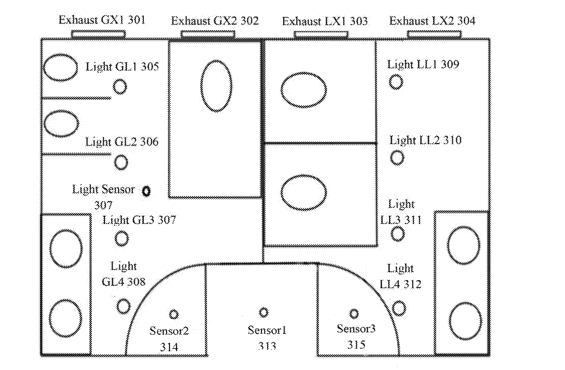
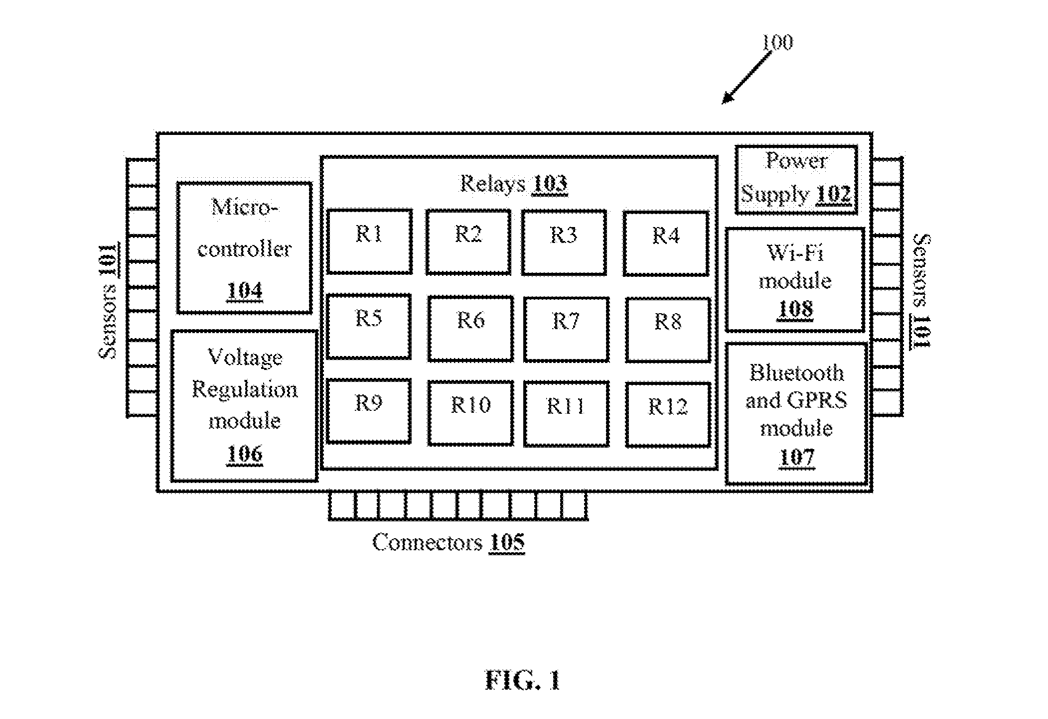
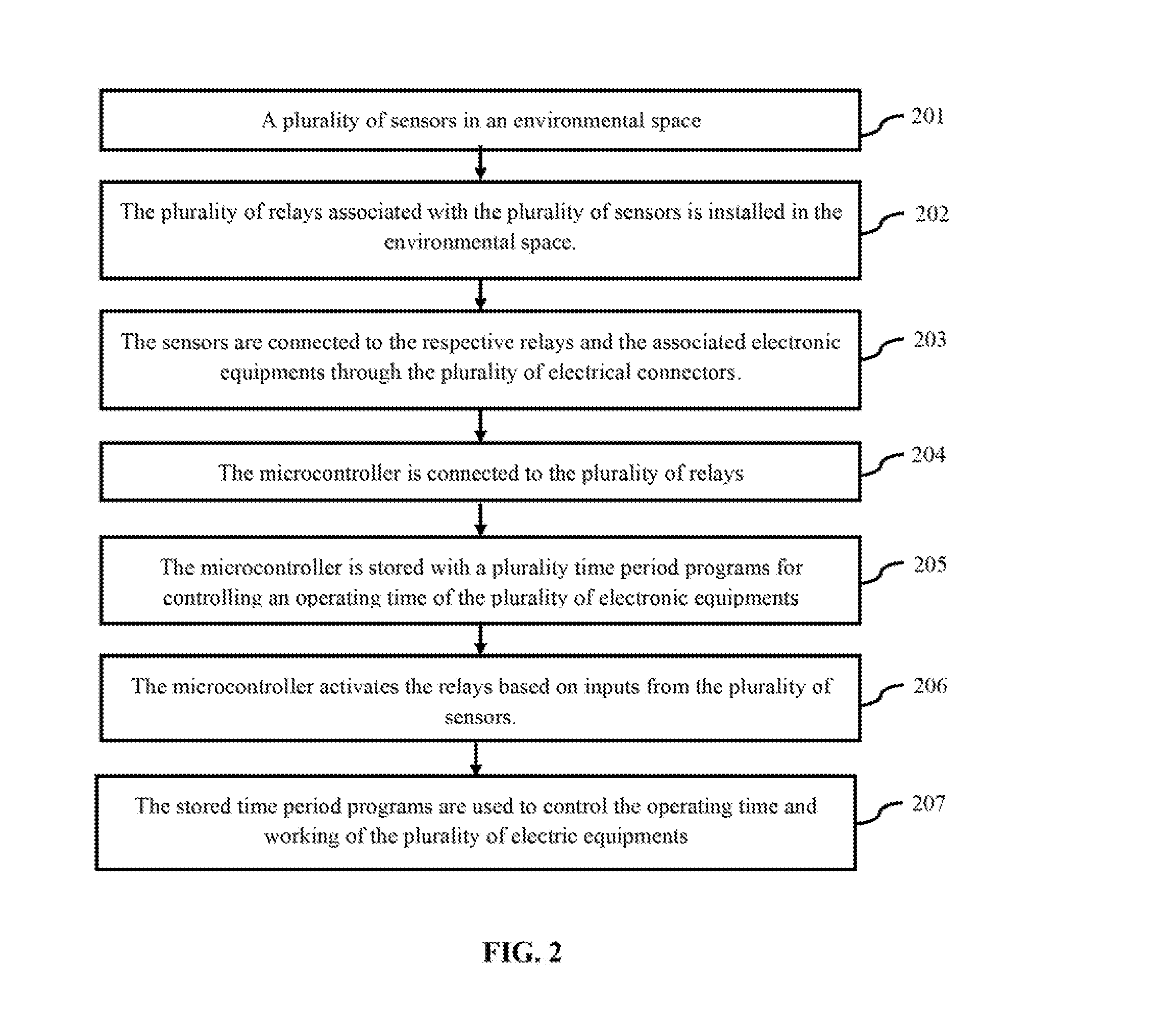
[0019]The primary object of the embodiments herein is to provide a method and system for managing and controlling a power supplied to electronic equipments such as lights, fans, exhaust, air conditioning, humidifiers, air cleaning equipment and the like in standalone places.

[0020]Another object of the embodiments herein is to eliminate a need for manual intervention by automating the entire functioning of a given space.

[0021]Yet another object of the embodiments herein is to eliminate a need for electrical switches that are used to manually control the connected equipments in a given space.

[0022]Yet another object of the embodiments herein is to provide a method and system for controlling a plurality of environmental conditions for a given space in-order to provide an optimal user experience.

[0023]Yet another object of the embodiments herein is to provide a method and system for reducing energy usage by humidifiers, air cleaning equipments, lighting and ventilation units.

[0024]Yet a...


PUM


Abstract

The embodiments herein provide an energy management system and method. The system comprises several electronic equipments installed in the standalone environmental space, several sensors in communication with a controller unit and a power supply. The sensors detect the environmental conditions or parameters of the environmental space. The relays are activated to switch on / off the electronic equipments depending on the sensor inputs. The controller unit regulates the operations of the electronic equipments through the relays based on sensors inputs. The sensors are activated at a predetermined set of time periods. The controller unit activates either one or more relays based on output from one or more sensors to control operation and operating time of the electronic equipments.

Description

CROSS REFERENCE TO RELATED APPLICATIONS[0001]The application is a National Phase Application filed with respect to the PCT Application No. PCT / IN2014 / 000644 filed on Oct. 7, 2014 with the title “AN ENERGY MANAGEMENT SYSTEM AND METHOD IN BUILDINGS”. The application further claims the priority of the Indian Provisional Patent Application with No. 3559 / CHE / 2013 filed on Oct. 8, 2013 with the title “AN ENERGY MANAGEMENT SYSTEM”. The contents of the above mentioned applications are incorporated in its entirety by reference herein.BACKGROUND[0002]1. Technical Field[0003]The embodiments herein generally relate to a power control and management system and particularly relates to a system and method for automatically switching electronic devices in standalone areas. The embodiments herein more particularly relates to a system and method for power control and management system or automatically switching electronic devices in standalone areas.[0004]2. Description of the Related Art[0005]In the...

Claims


Application Information

Patent Timeline
Patent Type & Authority Applications(United States)
IPC IPC(8): G05B15/02H02J3/00H01H47/00
CPCG05B15/02H02J3/00H01H47/00G05B19/42G05B2219/2642
Inventor KARIGUDDAIAH, AJITH
Owner KARIGUDDAIAH AJITH
Why Eureka
Try Eureka