Cartridge and Liquid Ejection Apparatus

a liquid ejection and cartridge technology, applied in the direction of printing, other printing apparatus, etc., can solve the problems of less smooth sliding, difficulty in insertion, and inability to smoothly attach cartridges, and achieve the effect of improving the attachment ability of cartridges

Active Publication Date: 2016-10-06
SEIKO EPSON CORP
View PDF1 Cites 9 Cited by
  • Summary
  • Abstract
  • Description
  • Claims
  • Application Information

AI Technical Summary

Benefits of technology

[0019](9) In the cartridge in any of the above-described modes, a rear restriction portion that restricts a tilt of the cartridge in the intersecting direction may be arranged in a lower face located on a vertically lower side, and on a trailing end side in the attaching direction. With this configuration, the risk of occurrence of liquid leakage and a contact failure of a terminal is reduced by su

Problems solved by technology

Such a position shift can be suppressed by making the width of a guide rail of a cartridge holder into which the cartridge is inserted the same as the width of the cartridge, but then the cartridge can slide less smoothly, resulting in difficulty of insertion.
For this reason, in the case where the aforementioned gap is not approp

Method used


Image

  • Cartridge and Liquid Ejection Apparatus
  • Cartridge and Liquid Ejection Apparatus
  • Cartridge and Liquid Ejection Apparatus

Examples


embodiment

A. Embodiment

A-1: Configuration of Printing Material Supply System

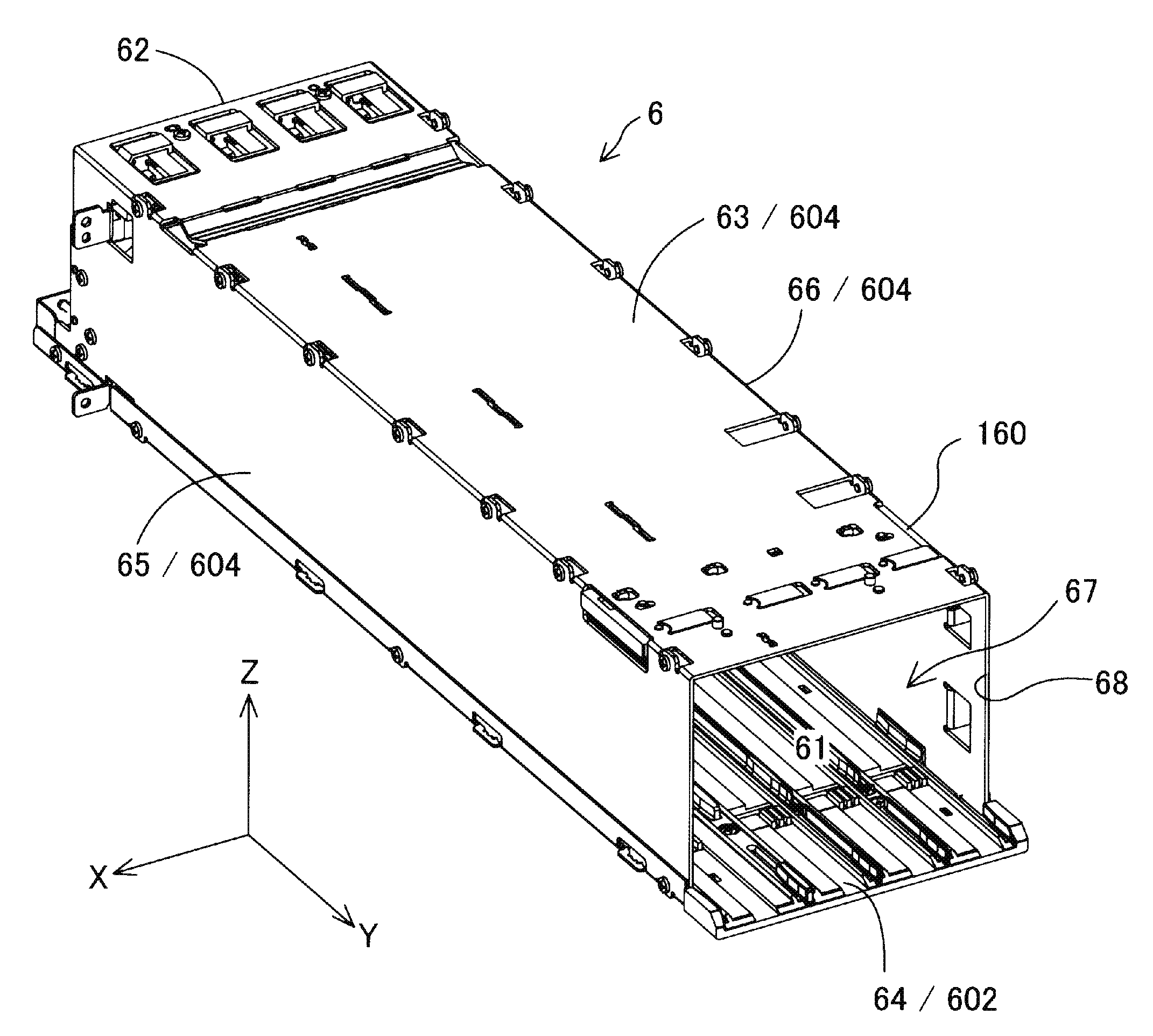
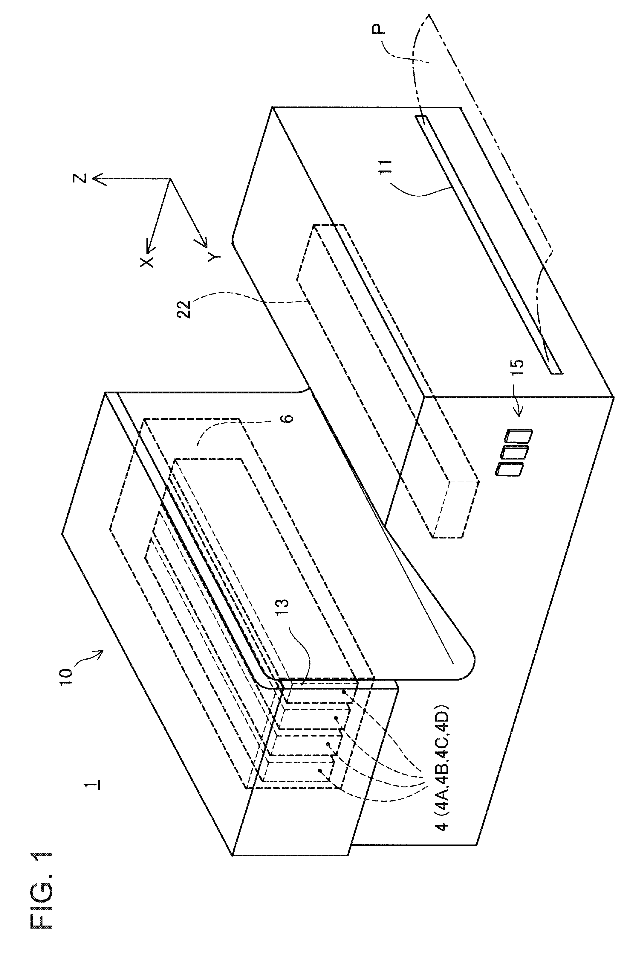
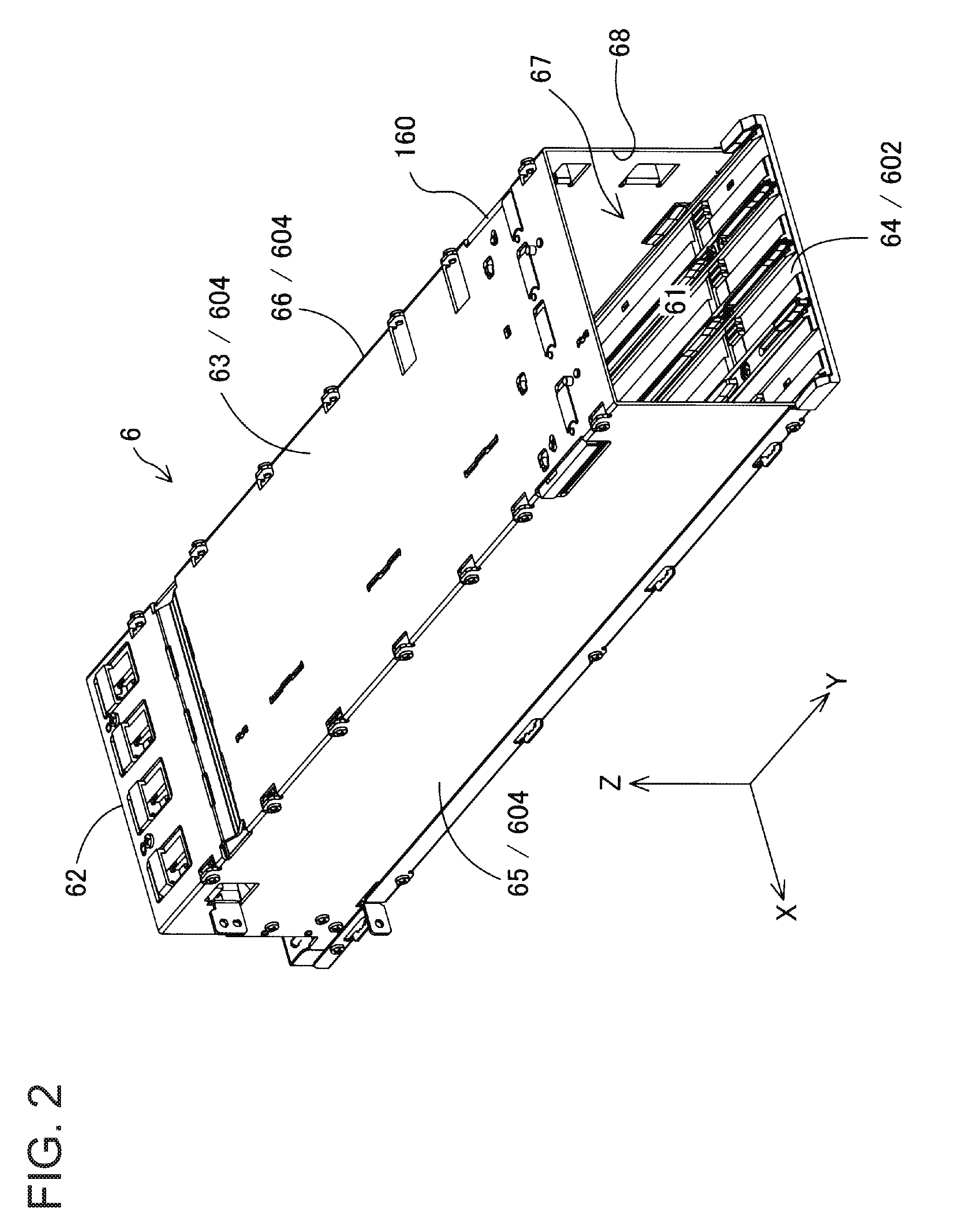
[0041]FIG. 1 is a perspective view showing a schematic configuration of a printing material supply system 1. The printing material supply system 1 includes a plurality of cartridges 4, and a printer 10, which serves as a liquid ejection apparatus. In the printing material supply system 1, the cartridges 4 are individually and detachably attached to a cartridge attachment portion 6 of the printer 10. Note that X, Y, and Z axes shown in FIG. 1 that are orthogonal to one another will be used as appropriate in the following descriptions of the shape of constituent members of the cartridge attachment portion 6 and the cartridge 4, positional relationships therebetween, and the like.

[0042]The printer 10 according to this embodiment is an inkjet line printer that discharges ink, which serves as liquid, from a line head 22. The line head 22 has ink ejection holes for ink of respective colors, which are black, yellow, magenta,...


PUM


Abstract

Accuracy in determination of the attaching direction of an elongated cartridge is improved. A cartridge 4A according to this embodiment to be attached to a printer includes an ink supply port 414 that supplies ink to the printer, a misinsertion prevention upper face projection portion 140 that engages with misinsertion prevention portions 671 of a misinsertion prevention plate 160 in a cartridge attachment portion 6, and restriction front upper face projection portions 430 that abut against a first guide rail 650 and a first guide rail 651 and restrict a tilt of the cartridge in an intersecting direction that intersects the attaching direction at the time of attachment. These restriction front upper face projection portions 430 are arranged between a leading end side in the attaching direction CS and the misinsertion prevention upper face projection portion 140.

Description

CROSS-REFERENCE TO RELATED APPLICATION[0001]This application claims priority under 35 U.S.C. §119 on Japanese Patent Application No. 2015-067811, filed Mar. 30, 2015. The content of this priority application is incorporated by reference in its entirety.BACKGROUND[0002]1. Technical Field[0003]The present invention relates to cartridges and liquid ejection apparatuses.[0004]2. Related Art[0005]Regarding a cartridge capable of supplying liquid to a liquid ejection apparatus, a mode of supplying ink to a printer, which is an example of a liquid ejection apparatus, has been hitherto known. A large flow of ink needs to be supplied in a printer capable of high-speed printing, a so-called line printer in which a plurality of ink ejection heads are linearly arranged, and the like. For this reason, an elongated cartridge having a suppressed height and a long depth has been proposed in order to contain a large amount of ink while avoiding an increase in the size of the apparatus (e.g., JP-A-20...

Claims


Application Information

Patent Timeline
IPC IPC(8): B41J2/175
CPCB41J2/1752B41J2/175B41J2/17513B41J2/17523B41J2/17553B41J29/13
Inventor KOIZUMI, YOSHIHIRONAKAMURA, HIROYUKI
Owner SEIKO EPSON CORP
Why Eureka
Try Eureka