Optical fiber connector with optical path direction changer

Inactive Publication Date: 2016-10-06
SENKO ADVANCED COMPONENTS HK
View PDF0 Cites 19 Cited by
  • Summary
  • Abstract
  • Description
  • Claims
  • Application Information

AI Technical Summary

Benefits of technology

[0007]It is an objective of the present invention to provide an optical fiber connector that changes the optical path direction of the con

Problems solved by technology

However, the use of mirror would necessary cause light to propagate outside of the optical fiber medium and causing possibly diffusional losses.
Although the claimed optical connector allows the optical fiber ribbon to be bent along the guiding face, the optical fiber ribbon is allowed to stray freely from the cu

Method used


Image

  • Optical fiber connector with optical path direction changer
  • Optical fiber connector with optical path direction changer
  • Optical fiber connector with optical path direction changer

Examples


Example

[0020]In the following description, apparatuses for connecting optical fibers and changing optical path directions of optical fibers and the likes are set forth as preferred examples. It will be apparent to those skilled in the art that modifications, including additions and / or substitutions may be made without departing from the scope and spirit of the invention. Specific details may be omitted so as not to obscure the invention; however, the disclosure is written to enable one skilled in the art to practice the teachings herein without undue experimentation.

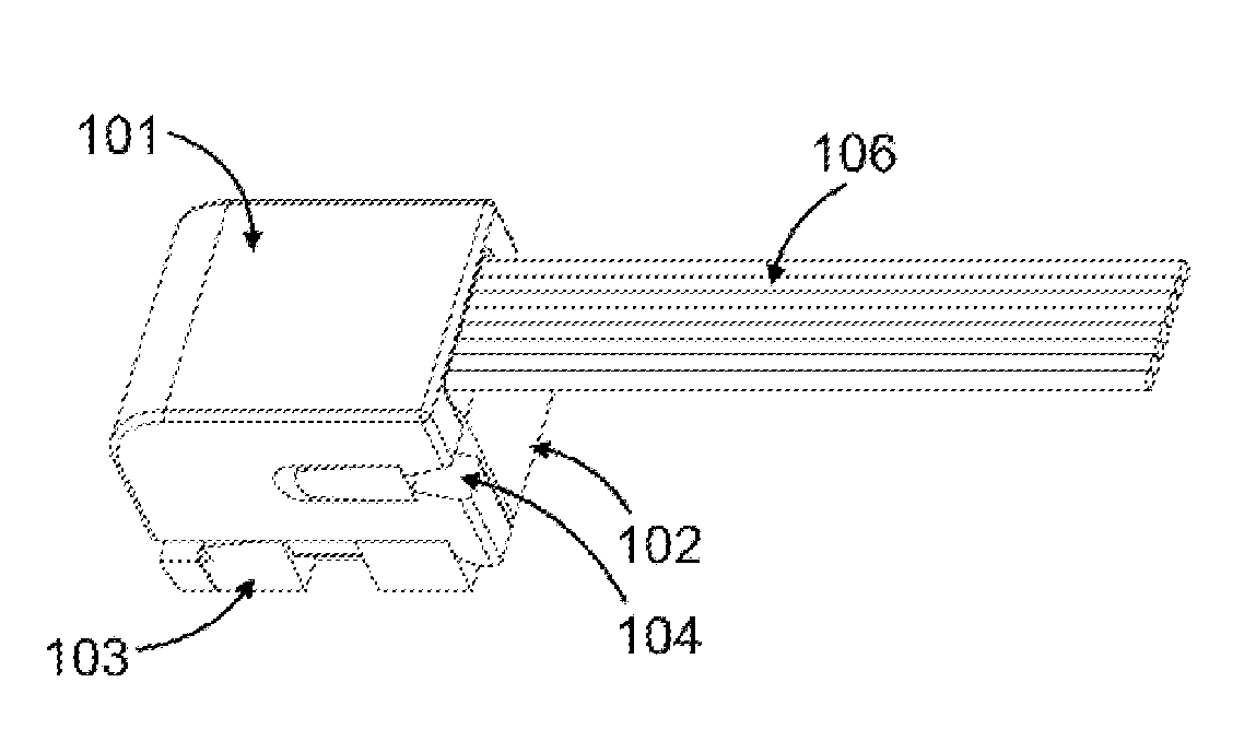
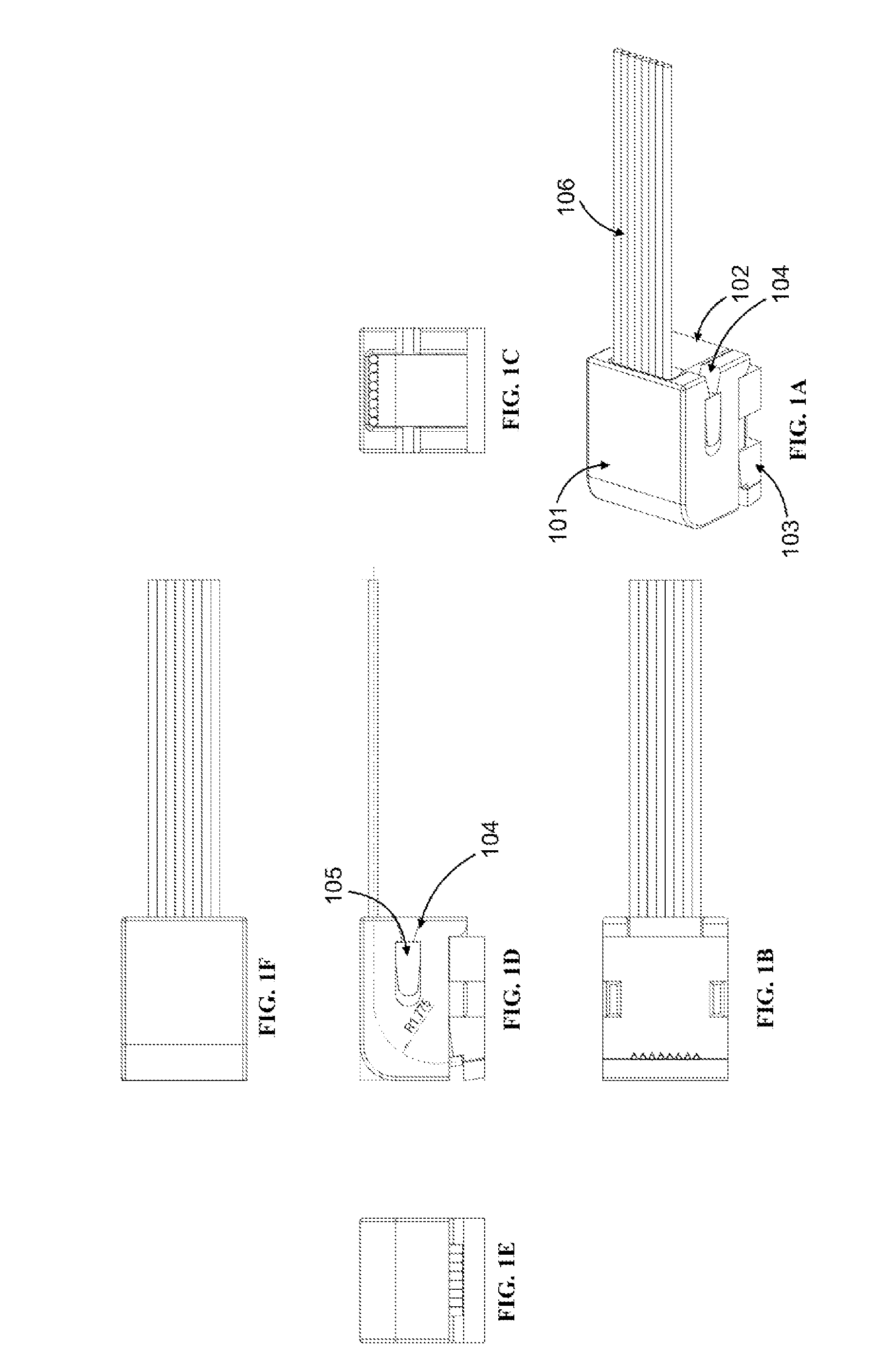
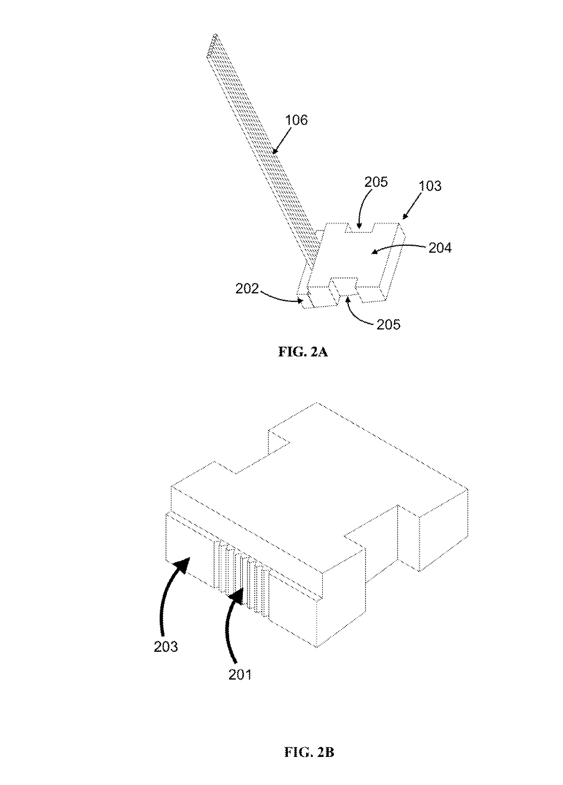
[0021]Referring to FIGS. 1A-1F. In accordance to one embodiment of the present invention, an optical path direction changing optical fiber connector for one or more optical fibers is provided, comprising: a cover 101, a retention block 102, and a base 103. The optical path direction changing optical fiber connector can be used to connect a single optical fiber or a ribbon of array of optical fibers. For illustration purposes, a...


PUM


Abstract

An optical path direction changing optical fiber connector, comprising: a base having an optical fiber mechanical splice at one edge of the base for securing a first end of an optical fiber ribbon; a retention block having a curved surface for guiding a portion of the optical fiber ribbon laid upon thereof, wherein the curved surface curving from a first end to a second end of the optical fiber ribbon such that the first end being at a bending angle to the second end of the optical fiber ribbon, wherein the curved guiding surface having a curvature radius of no more than approximately 2 mm, and wherein the retention block being positioned on top of the base; and a cover for covering the retention block and retaining the portions of the optical fiber ribbon laid upon the curved guiding surface of the retention block.

Description

COPYRIGHT NOTICE[0001]A portion of the disclosure of this patent document contains material, which is subject to copyright protection. The copyright owner has no objection to the facsimile reproduction by anyone of the patent document or the patent disclosure, as it appears in the Patent and Trademark Office patent file or records, but otherwise reserves all copyright rights whatsoever.FIELD OF THE INVENTION[0002]The present invention generally relates to a connection device for joining of optical fiber, and more particularly to an optical fiber connection device that changes the direction of the optical fiber or joins the optical fibers at an angle.BACKGROUND[0003]In optical communication systems, optical transmission between communication equipment is mostly facilitated by optical fibers. Optical fiber connectors are used at the light receiving or emitting ends of an optical fiber to interface optical communication equipment or to join two optical fibers end-to-end. Under certain ...

Claims


Application Information

Patent Timeline
IPC IPC(8): G02B6/38G02B6/42
CPCG02B6/4243G02B6/3839G02B6/3801G02B6/3829G02B6/3846G02B6/421G02B6/4214
Inventor IZUMI, KENJINI, ZHENDONGLI, ZHENHUA
Owner SENKO ADVANCED COMPONENTS HK
Why Eureka
Try Eureka