Discovery period configuration for small cell on/off

a technology of discovery period and small cell, applied in the field of small cell on/off techniques, can solve the problems of time-consuming initial scell configuration, and achieve the effect of reducing traffic delay

Inactive Publication Date: 2016-10-06
NEC CORP
View PDF1 Cites 17 Cited by
  • Summary
  • Abstract
  • Description
  • Claims
  • Application Information

AI Technical Summary

Benefits of technology

[0018]According to the above embodiment, a UE is able to detect the signal(s) for cell detection and RRM measurement in the configured discovery period by using legacy UE behavior of RRM measurement until LTE Release 11 to access a just turned-on cell with reduced traffic delay.
[0019]This has outlined the features and technical advantages of the present disclosure in order that the following description may be better understood. The features and advantages of the present disclosure will be more apparent from the following description in conjunction with the accompanying drawings. It is to be expressly understood, however, that each of the drawings is provided for the purpose of illustration and description only and is not intended as a definition of the limits of the present disclosure.

Problems solved by technology

However, the initial SCell configuration also costs time due to the similar process of cell synchronization and RRM measurement / reporting.

Method used


Image

  • Discovery period configuration for small cell on/off
  • Discovery period configuration for small cell on/off
  • Discovery period configuration for small cell on/off

Examples


first embodiment

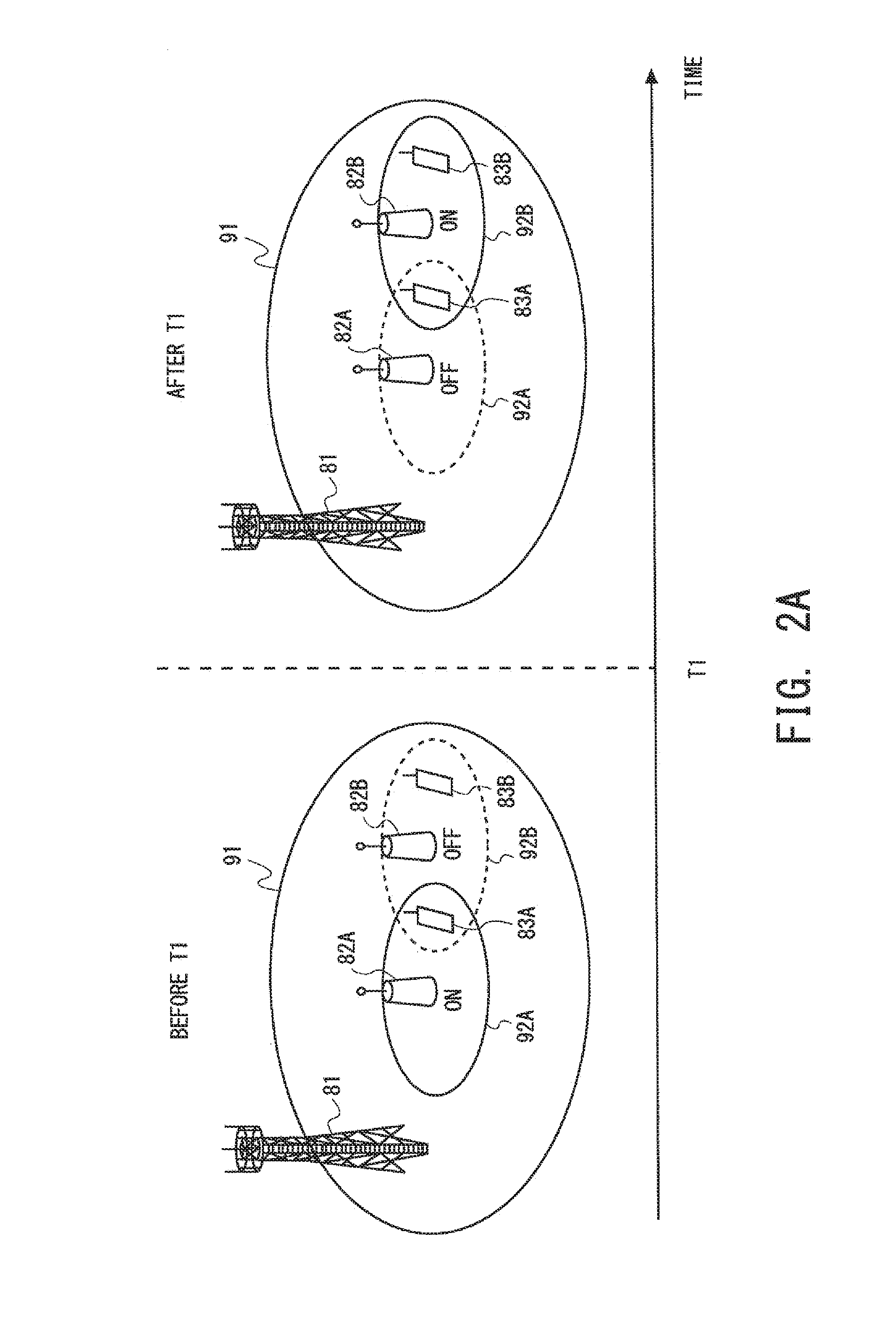
[0051]FIG. 5A conceptually illustrates an example of small cell ON / OFF behavior of the LPN 2 according to a first embodiment, where a network has already semi-statically configured the time T1 when the LPN 2A is being turned from ON to OFF and the LPN 2B is being turned from OFF to ON for user data transmission / reception. FIG. 5B shows a timing diagram illustrating operations of the MeNB 1, the LPNs 2A and 2B, and the UE 3A corresponding to FIG. 5A. The UE 3A in FIGS. 5A and 5B is in RRC_CONNECTED mode with the macro cell 10, controlled by the MeNB 1, as PCell and also served by the small cell 20A, controlled by the LPN 2A, as SCell during the ON period of the LPN 2A.

[0052]The Network configures the length DELTA.TD of the discovery period for the LPN 2B before the time T1. Note that, in drawings, “DELTA.” is denoted by the Greek letter delta. The discovery period is defined as a previous time period adjacent to the ON period. In other words, the discovery period immediately follows ...

second embodiment

[0059]FIG. 8A conceptually illustrates an example of small cell ON / OFF behavior of the LPN 2 according to a second embodiment, where the network has already semi-statically configured the time T1 when the LPN 2A is being turned from ON to OFF and the LPN 2B is being turned from OFF to ON for user data transmission / reception. FIG. 8B shows a timing diagram illustrating operations of the MeNB 1, the LPNs 2A and 2B, and the UE 3B corresponding to FIG. 8A. The UE 3B in FIGS. 8A and 8B is inter-eNB CA-capable and in RRC_CONNECTED mode with the macro cell 10, controlled by the Macro eNB, as PCell, but no SCell for the UE 3B is configured before T1. The network configures the discovery period of DELTA.TD for the LPN 2B before the time T1, which is same as that of the first embodiment. Different from UE 3A in FIGS. 5A and 5B, the UE 3B is firstly configured a SCell by the MeNB 1, and therefore the network only configure a new SCell of the LPN 2B. The detailed procedure is described as follo...

third embodiment

[0065]This embodiment illustrates a modification of the above-mentioned first and second embodiments. FIG. 10A conceptually illustrates an example of small cell ON / OFF behavior of the LPN 2 according to the third embodiment, where the network dynamically decided the time T1 when the LPN 2 is being turned from OFF to ON for user data transmission / reception. FIG. 10B shows a timing diagram illustrating operations of the MeNB 1 and the LPN 2 corresponding to FIG. 10A. The network may decide to turn on the LPN 2 based on, for example, traffic load at the MeNB 1, or traffic load at an LPN(s) adjacent to the LPN 2. The network, which dynamically decides the time T1 applied on the LPN 2, may include at least one of the MeNB 1, an LPN gateway (not shown), and an OAM system (not shown).

[0066]Returning to FIGS. 10A and 10B, the time T1 is defined as T1=T0+DELTA.TD by assuming the configured discovery period of DELTA.TD and the time T0 that is the starting time of the discovery period. How to ...


PUM


Abstract

In one embodiment, an apparatus, a system or a network (1) sets a discovery period for a node (2B). The discovery period is a time period in which the node (2B) sends a signal (e.g., PSS, SSS, and CRS) necessary for cell detection and radio measurement performed by a user equipment (3A) before a cell (20B), controlled by the node (2B), is to be turned on in order to send a signal (e.g., data signal) for either or both of user data reception and transmission. It is achieved, for example, that the user equipment (3A) is able to detect the signal (e.g., PSS, SSS, and CRS) for cell detection and radio measurement in the discovery period by using legacy behavior of radio measurement.

Description

TECHNICAL FIELD[0001]The present disclosure relates generally to a wireless communication system and, more specifically, to techniques of small cell on / off in Heterogeneous network.BACKGROUND ART[0002]Heterogeneous network with dense small cells 92 controlled by low power nodes (LPNs) 82 located in a macro cell 91 have been attracting much attention, as illustrated in FIG. 1. The macro cell 91 is controlled by a macro eNodeB (MeNB) 81. In 3GPP LTE Release 12 small cell enhancement study item (SCE SI), small cell on / off is a potential technique to avoid interference among small cells and ensure efficient operation for power saving. As introduced in NPL 1, small cell on / off technique includes turning on and off a small cell 92, where a cell here may refer to a component carrier (CC). As described in NPL 2, when a small cell 92 is on, an LPN 82 transmits signals necessary for a User Equipment (UE) 83 to receive data from the small cell 92, such as the reference signals used for measure...

Claims


Application Information

Patent Timeline
Patent Type & Authority Applications(United States)
IPC IPC(8): H04W48/16H04W28/02
CPCH04W28/0289H04W48/16H04W84/045
Inventor LIU, LEISHII, NAOTOFUTAKI, HISASHISHIKIDA, JUN
Owner NEC CORP
Why Eureka
Try Eureka