Systems and methods for active particle separation

a technology of active particle and filter, applied in magnetic separation, enzymology, instruments, etc., can solve the problem of increasing the pressure drop across the filter

Inactive Publication Date: 2016-10-13
ANCERA
View PDF6 Cites 4 Cited by
  • Summary
  • Abstract
  • Description
  • Claims
  • Application Information

AI Technical Summary

Benefits of technology

[0057]The above-noted embodiments, as well as other embodiments, will become even more evident with reference to the following detailed description and associated drawing, a brief description of which is provided below.

Problems solved by technology

Mechanical exclusion, via well-known filtration is, by its very nature, prone to clogging, and also subsequent increases in pressure drop across the filter as the filter becomes more and more clogged.

Method used


Image

  • Systems and methods for active particle separation
  • Systems and methods for active particle separation
  • Systems and methods for active particle separation

Examples


Embodiment Construction

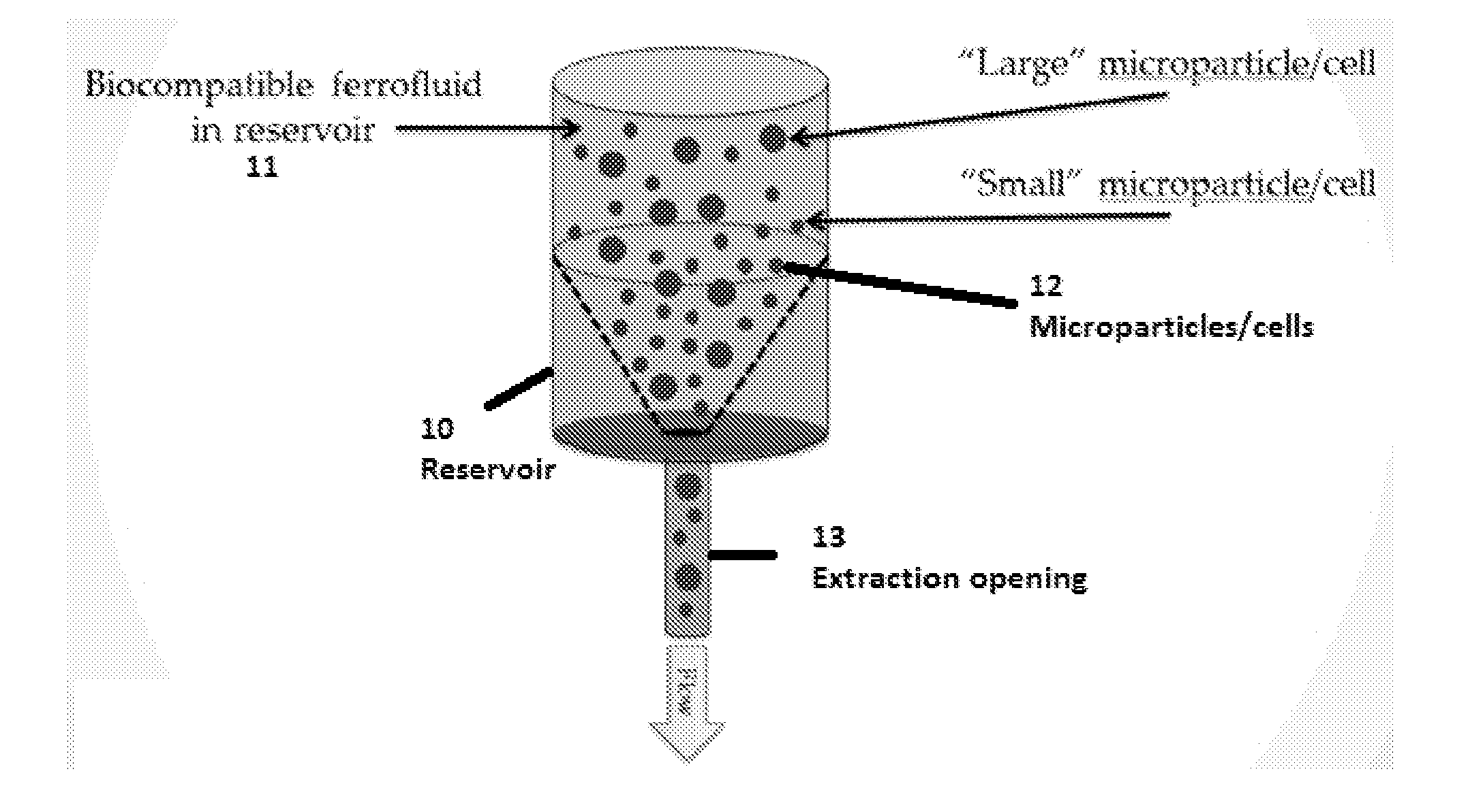
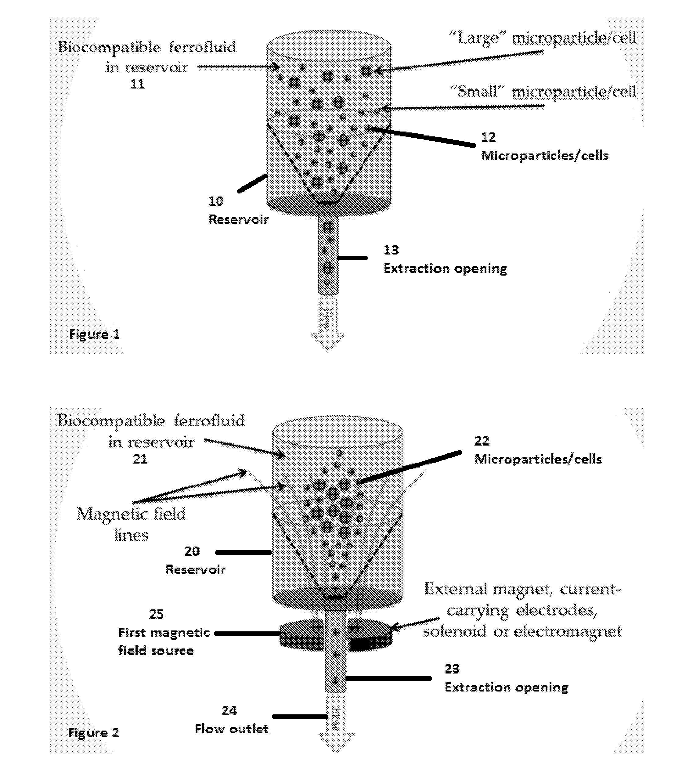
[0063]As shown in FIG. 1, a reservoir 10 containing a ferrofluid 11 (which in some embodiments is biocompatible) and a mixture of microparticles / cells 12 having different sizes (in some embodiments). In FIG. 1, no external forces are applied to the fluid, reservoir and / or particles, and ignoring buoyancy issues, a random mixture of particles may flow through an extraction opening 13 of the reservoir.

[0064]FIG. 2 illustrates some embodiments, where a reservoir 20 containing a ferrofluid 21 with a mixture of microparticles 22 of different sizes, and includes at least one magnetic source 25 for applying a magnetic field to the ferrofluid 21, which may be arranged either internal or external to the reservoir 20. The particles 22 include biological cells and moieties. The magnetic field may be configured to exert one or more forces on the ferrofluid 21 and may be generated via, for example, one or more: external magnets, current-carrying electrodes, solenoid, and electromagnets. In one e...


PUM

PropertyMeasurementUnit
pore sizesaaaaaaaaaa

Abstract

A device and method for extracting particles contained in a ferrofluid medium are provided. Such methods may comprise suspending particles of different sizes in a ferrofluid medium and containing the ferrofluid medium in a cylindrical reservoir, and applying a first magnetic field to at least a portion of the reservoir. The first magnetic field is configured to indirectly exert a force on at least a portion of the particles of a predetermined size, and direct the portion of particles in a desired direction.

Description

RELATED APPLICATIONS[0001]This application claims benefit under 35 USC 119(e) of U.S. provisional patent application Nos. 61 / 794,885, filed Mar. 15, 2013, and entitled, “PCB-Based Magnetic Excitation Approach” the entire disclosure of which is herein incorporated by reference in its entirety.FIELD OF THE DISCLOSURE[0002]The present disclosure relates to methods and systems for extracting particles from ferrofluids.BACKGROUND OF THE DISCLOSURE[0003]WO2011 / 071912 and WO2012 / 057878 presents systems and methods for separating microparticles or cells contained in a ferrofluid medium using magnetic forces. The magnitude of these forces depend, in part, on the volume of the non-magnetic particles (e.g., moieties) for separation / targeting. Moreover, a larger cell or microparticle displaces a larger ferrofluid volume, and experiences larger forces.[0004]Mechanical exclusion, via well-known filtration is, by its very nature, prone to clogging, and also subsequent increases in pressure drop ac...

Claims


Application Information

Patent Timeline
Patent Type & Authority Applications(United States)
IPC IPC(8): B03C1/32C12N13/00C02F1/48B03C1/28C02F1/44
CPCB03C1/32B03C1/288B03C2201/18C02F1/488C12N13/00C02F1/44G01N35/0098B03C1/023B03C1/0332B03C1/0335B03C1/253B03C2201/26
Inventor KOSER, HUR
Owner ANCERA
Why Eureka
Try Eureka