

Flash gas bypass evaporator
- Summary
- Abstract
- Description
- Claims
- Application Information
AI Technical Summary
Benefits of technology
Problems solved by technology
Method used
Image

Examples
Embodiment Construction
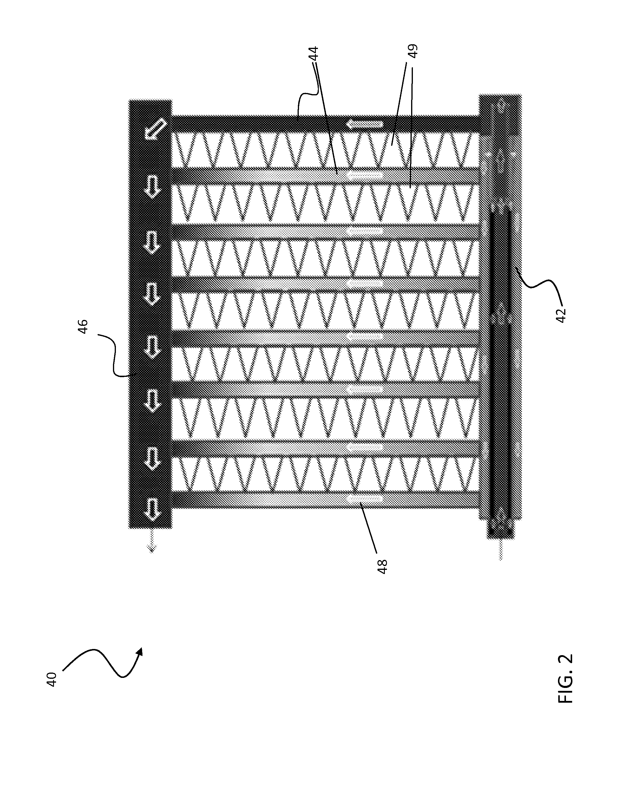
[0014]Referring now to FIG. 2, a parallel flow heat exchanger 40 includes a fluid distribution manifold 42 and a plurality of parallel disposed and longitudinally spaced tubes 44 extending between the fluid distribution manifold 42 and a fluid collection manifold 46. The tubes 44 define parallel heat exchanger flow passes 48 opening into the respective interior chambers of the fluid distribution manifold 42 and the fluid collection manifold 46 for conveying fluid from the fluid distribution manifold 42 to the fluid collection manifold 46. A plurality of fins 49, mounted to the exterior of the plurality of tubes 44, serve as a secondary heat transfer surface configured to transfer heat from the air to the refrigerant flowing through the tubes 44. The tubes 44 of the heat exchanger 40 are depicted as flattened multichannel tubes wherein each of the parallel flow passes 48 is subdivided into a plurality of “microchannel” or “minichannels” flow passages. Microchannel and minichannel tub...
PUM
| Property | Measurement | Unit |
|---|---|---|
| Centrifugal force | aaaaa | aaaaa |
| Flow rate | aaaaa | aaaaa |
| Diameter | aaaaa | aaaaa |
Abstract
Description
Claims
Application Information