Liquefied gas treatment system

a technology of liquefied gas and treatment system, which is applied in the direction of machines/engines, machine/engine discharging methods, lighting and heating apparatus, etc., can solve the problems of different temperature and pressure of liquefied gas required by a source of demand, such as an engine, and achieve the effect of improving liquefaction efficiency

Inactive Publication Date: 2014-12-04
HYUNDAI HEAVY IND CO LTD
View PDF8 Cites 8 Cited by
  • Summary
  • Abstract
  • Description
  • Claims
  • Application Information

AI Technical Summary

Benefits of technology

[0010]Various embodiments relate to a liquefied gas treatment system that pressurizes and supplies boil-off gas to a liquefied gas-consuming unit, decompresses and liquefies part of the boil-off gas, and supplies flash gas, derived from a liquefaction process, to a boil-off gas heat exchanger so as to use the boil-off gas for heat exchange to improve liquefaction efficiency.
[0011]In addition, the present invention provides a liquefied gas treatment system capable of significantly improving reliquefaction efficiency of boil-off gas by re-circulating flash gas by a boil-off gas compressor and using the flash gas as a medium for cooling the boil-off gas.

Problems solved by technology

However, the temperature and pressure of liquefied gas required by a source of demand, such as an engine, may be different from a state of liquefied gas stored in a liquefied gas storage tank.

Method used


Image

  • Liquefied gas treatment system
  • Liquefied gas treatment system
  • Liquefied gas treatment system

Examples


first embodiment

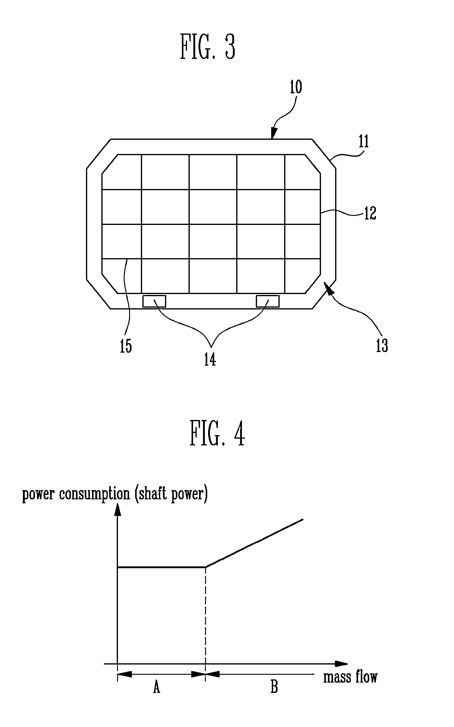
[0043]As described above, according to the present invention, since the pressure tank type liquefied gas storage tank 10 that includes the vacuum insulation unit 13 between the outdoor tank 11 and the indoor tank 12 is used, generation of boil-off gas may be reduced, and the liquefied gas storage tank 10 may be prevented from being damaged despite increase in internal pressure.

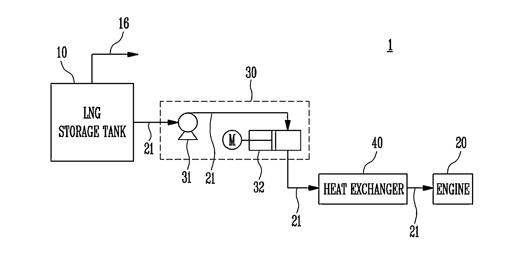
[0044]According to a first embodiment of the present invention, boil-off gas, generated from the liquefied gas storage tank 10, may be efficiently used by supplying the boil-off gas to the boil-off gas compressor 50 to heat the boil-off gas or by pressurizing and supplying the boil-off gas as fuel to the liquefied gas-consuming unit 20.

[0045]A forcing vaporizer 19 may be provided downstream of the liquefied gas storage tank 10. When the mass flow of the boil-off gas is insufficient, the forcing vaporizer 19 may operate to increase the mass flow of the boil-off gas supplied to the liquefied gas-consuming unit 2...

second embodiment

[0091]As described above, according to the present invention, since the pressure tank type liquefied gas storage tank 10 that includes the vacuum insulation unit 13 between the outdoor tank 11 and the indoor tank 12 is used, generation of boil-off gas may be reduced, and the liquefied gas storage tank 10 may be prevented from being damaged despite increase in internal pressure.

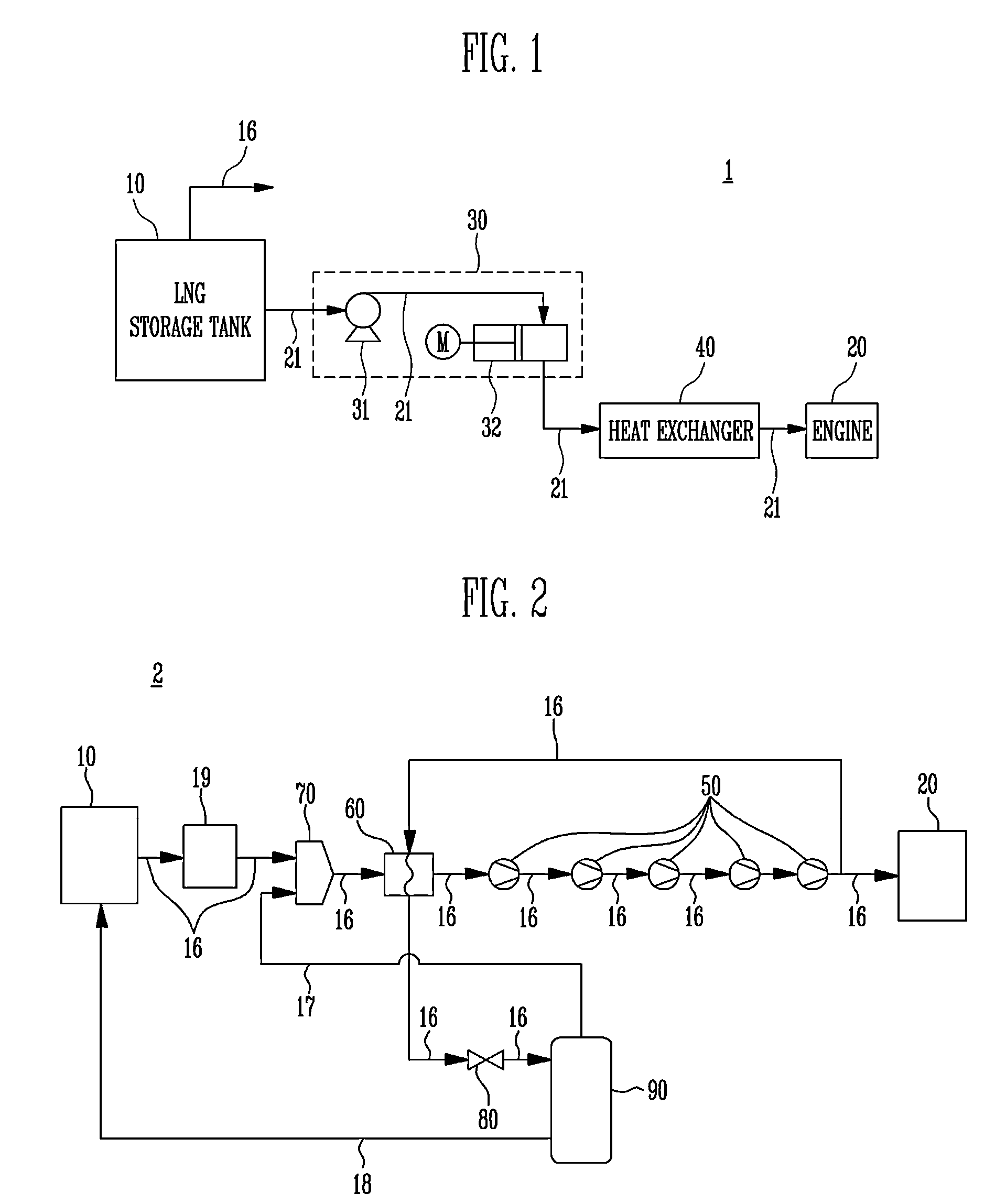
[0092]According to a second embodiment of the present invention, boil-off gas, generated from the liquefied gas storage tank 10, may be efficiently used by supplying the boil-off gas to the boil-off gas compressor 50 to heat the boil-off gas or by pressurizing the boil-off gas to supply the pressurized boil-off gas as fuel to the liquefied gas-consuming unit 20.

[0093]A forcing vaporizer (not illustrated) may be provided downstream of the liquefied gas storage tank 10. When a mass flow of the boil-off gas is insufficient, the forcing vaporizer may operate to increase the mass flow of the boil-off gas supplied t...

third embodiment

[0123]FIG. 7 is a conceptual view of a liquefied gas treatment system according to the invention. FIG. 8 is a graph illustrating power consumption with respect to mass flow of a boil-off gas compressor in a general liquefied gas treatment system.

[0124]A liquefied gas treatment system 3 is described with reference to FIG. 7. The liquefied gas treatment system 3 may be equal to the liquefied gas treatment system 2, except for a mixer 70 and a flash gas recovery line 18A. The same reference numerals or the same reference designators may denote the same or corresponding elements of the earlier described embodiment, and a detailed description thereof will be omitted.

[0125]According to a third embodiment of the present invention, the flash gas, which is supplied from the vapor-liquid separator 90 and heat-exchanged by the boil-off gas heat exchanger 60, may not be exhausted to the outside but may be recovered for use. According to a third embodiment of the present invention, the flash gas...


PUM


Abstract

A liquefied gas treatment system according to an embodiment of the present invention includes a boil-off gas heat exchanger exchanging heat between boil-off gas, pressurized by a boil-off gas compressor and recovered along a boil-off gas supply line branching off upstream of a liquefied gas-consuming unit, and the boil-off gas supplied from a liquefied gas storage tank, wherein the boil-off gas heat exchanger cools the boil-off gas, recovered along the boil-off gas supply line, with the boil-off gas, supplied from the liquefied gas storage tank, or flash gas, supplied through a vapor recovery line.

Description

CROSS-REFERENCE TO RELATED APPLICATION[0001]The present application claims priority to Korean patent application number 10-2013-0061483 filed on May 30, 2013 and Korean patent application number 10-2013-0085192 filed on Jul. 19, 2013, in the Korean Intellectual Property Office, the entire disclosure of which is incorporated by reference herein.BACKGROUND[0002]1. Field of Invention[0003]An embodiment relates generally to a liquefied gas treatment system.[0004]2. Description of Related Art[0005]With recent technological advances, liquefied gas, such as liquefied natural gas or liquefied petroleum gas, which replaces gasoline or diesel, has come into widespread use.[0006]Liquefied natural gas is natural gas that is converted into liquid form by cooling methane obtained by refining natural gas extracted from the gas field. Liquefied gas is a colorless, transparent liquid, and it is a fine fuel that produces little pollution and has a high calorific value. On the other hand, liquefied pe...

Claims


Application Information

Patent Timeline
Patent Type & Authority Applications(United States)
IPC IPC(8): F17C7/04
CPCF17C7/04F25J1/0025F25J1/0035F25J1/004F25J1/0045F25J1/0202F25J1/0254F25J1/0298F17C2221/033F25J2290/62F17C2201/0157F17C2201/052F17C2203/0391F17C2203/0629F17C2203/0639F17C2223/0161F17C2223/033F17C2223/035F17C2223/043F17C2225/0123F17C2225/033F17C2225/035F17C2227/0164F17C2227/0306F17C2227/0309F17C2227/036F17C2250/0443F17C2265/036F17C2265/037F17C2265/066F17C2270/0105F02M21/0221F25J1/023F17C9/02Y02T10/30F25J2240/02F25J2240/40
Inventor BAEK, EUN SUNG
Owner HYUNDAI HEAVY IND CO LTD
Why Eureka
Try Eureka