Device and method for performing multistage flash, resolution and separation on synthetic ammonia decarburization absorption tower bottom pregnant solution

An absorption tower and a technology for synthesizing ammonia, applied in separation methods, dispersed particle separation, chemical instruments and methods, etc., can solve the problem of increasing the circulating volume of lean liquid and semi-lean liquid, increasing the processing capacity and energy consumption of the absorption tower, increasing Problems such as the gas phase temperature at the bottom of the absorption tower can be eliminated to achieve the effects of eliminating the bottleneck of the absorption tower, lowering the temperature, and reducing the cost of expansion

Active Publication Date: 2016-10-12
SUN YAT SEN UNIV
View PDF4 Cites 9 Cited by
  • Summary
  • Abstract
  • Description
  • Claims
  • Application Information

AI Technical Summary

Problems solved by technology

Due to the fact that the analysis process of the rich liquid at the bottom of the decarburization absorption tower of synthetic ammonia lacks the pressure combination with the compressor of the downstream urea section, and the comprehensive optimization process innovation design and global integration of pressure energy are not considered, the main problems of the existing synthetic ammonia decarburization process are as follows: (1 ) is to separate the CO in the rich liquid at the bottom of the absorption tower 2 , the high-pressure rich liquid is decompressed to normal pressure through a hydraulic turbine and a throttle valve to obtain the final low-pressure CO 2 After the product, it needs CO 2 The compressor is boosted and sent to the downstream urea section to complete the synthesis reaction, and the rich liquid at the bottom of the absorption tower is desorbed for CO 2 There are repeated step-down and step-up processes in the process, which invisibly increases the consumption of pressure energy; (2) the high-temperature low-change gas heat is not fully utilized, which increases the temperature of the gas phase entering the bottom of the absorption tower and reduces the temperature of the absorption tower. efficiency, increasing the circulation volume of lean liquid and semi-lean liquid, virtually increasing the processing capacity and energy consumption of the absorption tower

Method used


Image

  • Device and method for performing multistage flash, resolution and separation on synthetic ammonia decarburization absorption tower bottom pregnant solution
  • Device and method for performing multistage flash, resolution and separation on synthetic ammonia decarburization absorption tower bottom pregnant solution
  • Device and method for performing multistage flash, resolution and separation on synthetic ammonia decarburization absorption tower bottom pregnant solution

Examples


Embodiment 1

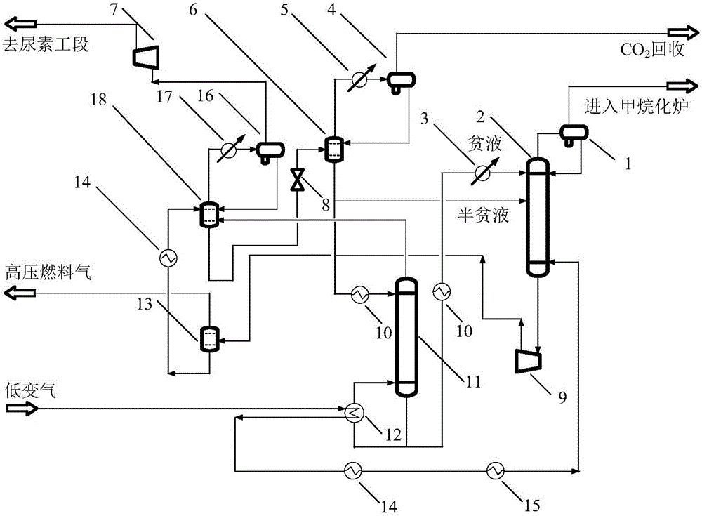
[0030] Such as figure 1 As shown, a multi-stage flash analysis and separation device for decarburization of the rich liquid at the bottom of the absorption tower for synthetic ammonia, including the separation tank 1 at the top of the absorption tower, CO 2 Absorption tower 2, water condenser 3, low-pressure flash tank top separation tank 4, low-pressure flash tank top condenser 5, low-pressure flash tank 6, CO 2 Compressor 7, throttle valve 8, hydraulic turbine 9, lean liquid / semi-lean liquid heat exchanger 10, desorption tower 11, low gas change / desorption tower bottom liquid heat exchanger 12, first-stage high-pressure flash tank 13 , Low gas change / first stage flash tank bottom liquid heat exchanger 14, low gas change / demineralized water heat exchanger 15, secondary high pressure flash tank top separation tank 16, secondary high pressure flash tank top condenser 17. Secondary high-pressure flash tank 18;

[0031] Among them, the rich liquid outlet at the bottom of the ab...

Embodiment 2

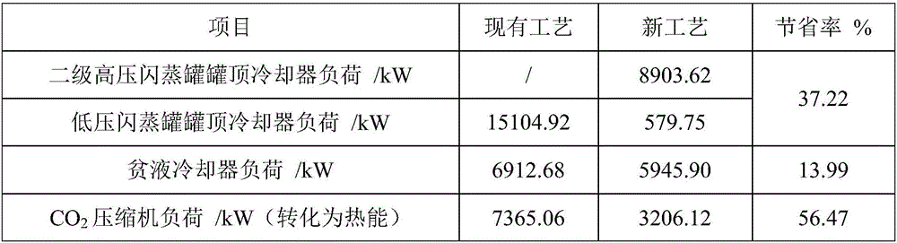
[0061] In Example 2, the multi-stage flash separation and analysis method of the present invention is specifically described by taking a 910,000-ton / year synthetic ammonia decarburization absorption tower rich liquid device as an example in a chemical plant.

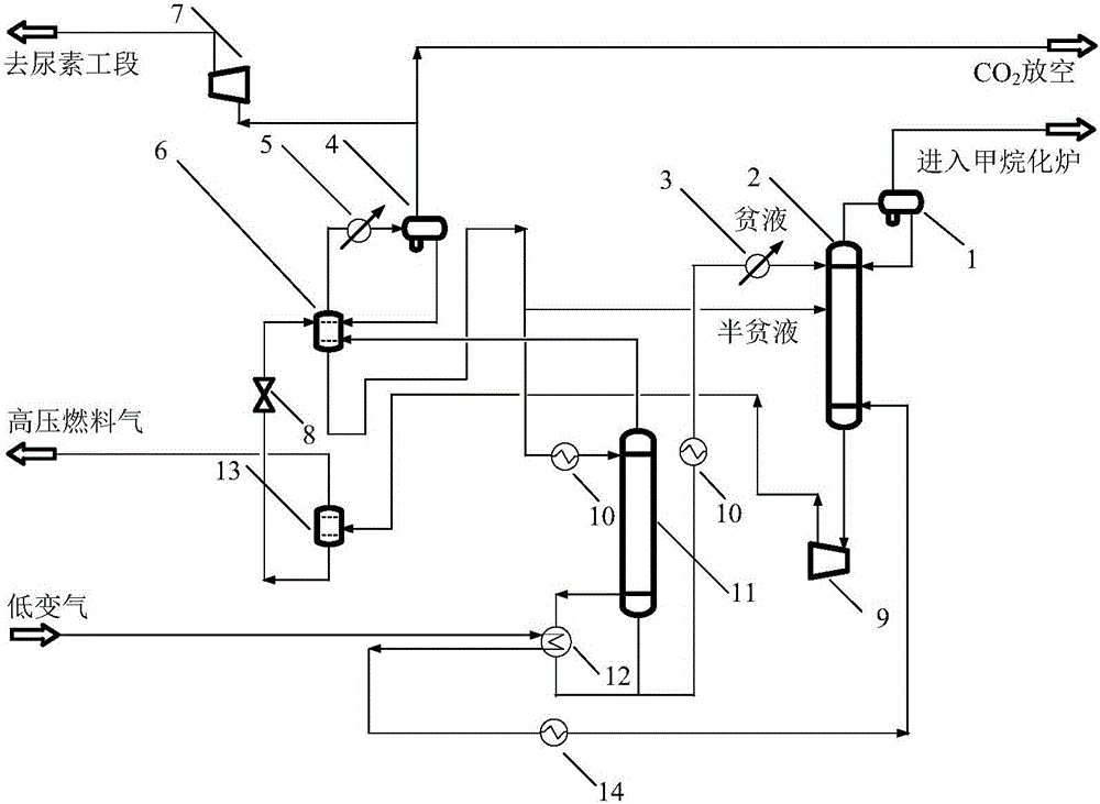
[0062] Table 4 is the 910,000 tons / year synthetic ammonia decarburization absorption tower bottom rich liquid analytical separation comparative example 1 and embodiment 1 device raw materials and composition, the raw materials, composition, product regulations and absorbent (MEA) of the two processes are exactly the same, Among them, the embodiment process is as follows figure 1 As shown, compare for example figure 2 shown. In Example 1, the medium and low-change gas is cooled to 40°C by three heat exchangers and then enters the absorption tower. The liquid phase pressure at the bottom of the first-stage high-pressure flash tank is 1.2MPa, and after heat exchange, the temperature is raised to 90°C and then enters the s...


PUM


Abstract

The invention discloses a device and a method for performing multistage flash, resolution and separation on a synthetic ammonia decarburization absorption tower bottom pregnant solution. The absorption tower bottom pregnant solution enters into a primary high-pressure flash tank after being decompressed; a flashing gas phase is used as a fuel gas, and a flashing liquid phase enters into a secondary high-pressure flash tank after being subjected to heat exchange; after being cooled and separated, a gas phase of the secondary high-pressure flash tank enters into a CO2 compressor so as to be conveyed to a urea workshop section, and a separated liquid phase flows back to the secondary high-pressure flash tank, and a flashing liquid phase enters into a low-pressure flash tank after being decompressed; after being cooled and separated, the gas phase of the low-pressure flash tank enters into a CO2 recovery device, a separated liquid phase flows back to the low-pressure flash tank, the flashing liquid phase partially enters into a resolution tower after being subjected to heat exchange, and the residual part enters into an absorption tower; resolution tower overhead gas enters into a secondary high-pressure flash tank, the tower bottom solution partially returns to the tower after exchanging heat with low-change gas, the residual part enters the absorption tower after being cooled, and the absorption tower overhead gas is fed into a methanation furnace through a separator. A multistage flash evaporation and resolution process is adopted, so that the CO2 yield is improved and the energy consumption of an absorption tower bottom pregnant solution resolving process is reduced.

Description

technical field [0001] The invention relates to a multi-stage flash analysis and separation method for the rich liquid at the bottom of the absorption tower for decarburization of synthetic ammonia, in particular to realize the CO in the rich liquid at the bottom of the absorption tower by mixing the multi-stage flash analysis and absorption process 2 Gas separation and purification. Background technique [0002] In order to control the purity and ratio of feedstock for ammonia synthesis reaction and avoid catalyst poisoning, the CO in the low-change gas from the reaction part 2 It must be removed in time before the ammonia synthesis process. Alcoholamine (methyldiethanolamine, MDEA, monoethanolamine, MEA) as CO 2 The absorbent has obvious advantages: low absorption and desorption temperature, small solution heat capacity, low regeneration energy consumption, high gas purification purity, no corrosion in the solution, low solvent vapor pressure, and low solvent consumption...

Claims


Application Information

Patent Timeline
Patent Type & Authority Applications(China)
IPC IPC(8): B01D53/14B01D53/18
CPCB01D53/1425B01D53/1475B01D53/18Y02C20/40
Inventor 刘雪刚赵悦张冰剑陈清林何畅何昌春
Owner SUN YAT SEN UNIV
Why Eureka
Try Eureka