Ultra-low emission natural gas dehydration unit with continuously fired reboiler

a technology of natural gas dehydration unit and continuously fired reboiler, which is applied in the direction of gaseous fuel, separation process, fuel, etc., can solve the problem that additional or supplemental stripping gas is not required to adequately regenerate glycol, and achieve the effect of effectively destroying flash gas

Inactive Publication Date: 2011-10-13
WITHERSPOON JOSEPH A
View PDF0 Cites 10 Cited by
  • Summary
  • Abstract
  • Description
  • Claims
  • Application Information

AI Technical Summary

Benefits of technology

[0016]It has been recognized that it would be advantageous to develop an ultra-low emission glycol dehydration unit. In addition, it has been recognized that it would be advantageous to develop a dehydration unit that continuously utilizes all of the flash gas at the burner of the reboiler; maintains glycol temperature; eliminates the jet-gas system and power-gas pump for hot glycol circulation; uses a flash gas contactor to provide usable fuel gas to the reboiler, even during the winter; and utilizes the existing glycol pump to circulate hot glycol as a heating fluid to prevent freezing of piping and equipment during the winter that can be bypassed in the summer.
[0020]In accordance with a more detailed aspect of the present invention, the method includes flowing dry desiccant to a flash gas contactor on the flash tank, thus absorbing water from the flash gas and rendering the flash gas as a usable fuel gas during winter operation and effectively destroying the flash gas without venting the gas to atmosphere and without requiring a waste-gas combustor for VOC and benzene destruction.

Problems solved by technology

Since the reboiler is continuously fired, sufficient stripping gas is generated from the wet glycol in the reboiler; thus, additional or supplemental stripping gas is not required to adequately regenerate the glycol.

Method used


Image

  • Ultra-low emission natural gas dehydration unit with continuously fired reboiler
  • Ultra-low emission natural gas dehydration unit with continuously fired reboiler

Examples


Embodiment Construction

[0023]It will be readily understood that the components of the present invention, as generally described and illustrated in the drawing herein, could be arranged and designed in a wide variety of different configurations. Thus, the following more detailed description of the embodiments of the system and method of the present invention, as represented in the drawing, is not intended to limit the scope of the invention, but is merely representative of various embodiments of the invention. The illustrated embodiments of the invention will be best understood by reference to the drawing, wherein like parts are designated by like numerals throughout.

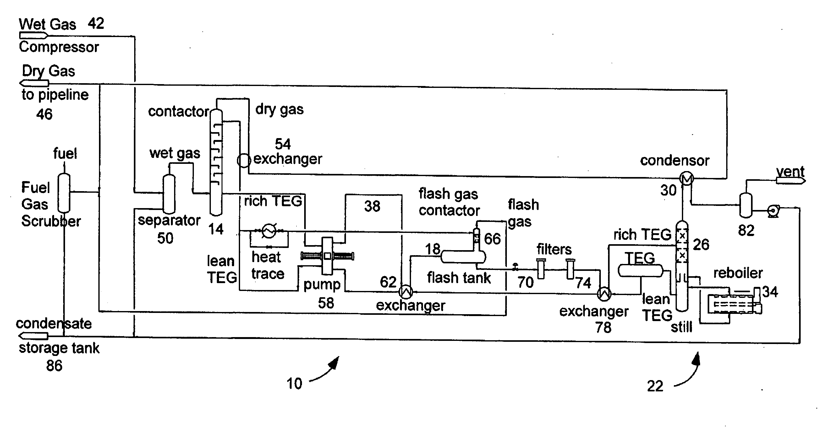
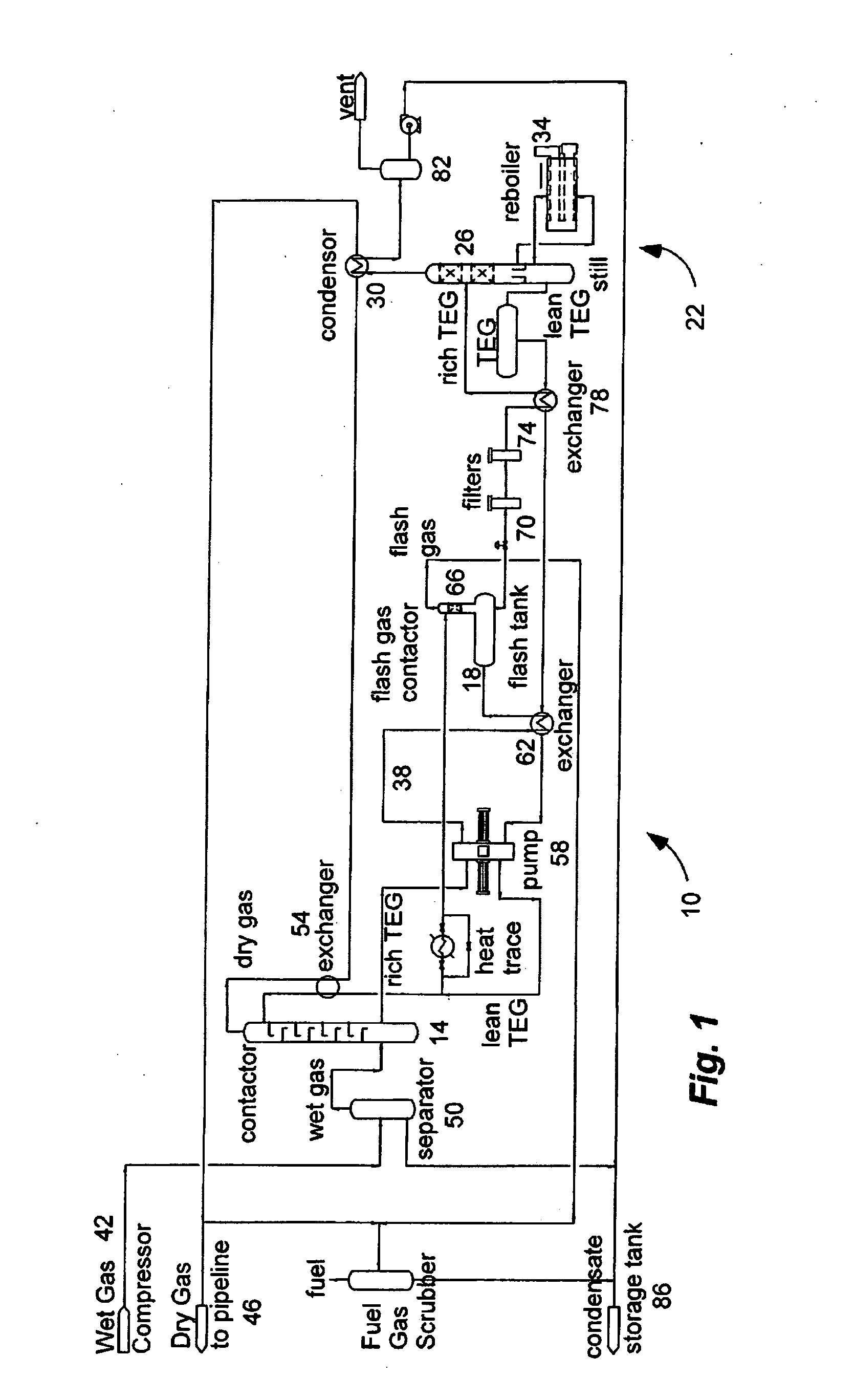
[0024]As illustrated in FIG. 1, a natural gas dehydration system, indicated generally at 10, in an example implementation in accordance with the invention is shown for dehydrating natural gas. Such a system can be used in the field at remote operations adjacent one or more well heads for processing natural gas prior to transporting in a pipeli...


PUM

PropertyMeasurementUnit
temperatureaaaaaaaaaa
boiling pointaaaaaaaaaa

Abstract

A natural gas dehydration system and method includes a contactor, a flash tank, and a still interconnected by a desiccant circulation system. A continuously fired reboiler is coupled to the still and the flash tank to bum the flash gas from the flash tank and heat the desiccant.

Description

1. RELATED APPLICATION[0001]This application claims the benefit of U.S. Provisional Pat. App. Ser. No. 61 / 322,022, filed Apr. 8, 2010, and entitled “NATURAL GAS DEHYDRATION UNIT WITH CONTINUOUSLY FIRED REBOILER.”BACKGROUND [0002]2. The Field of the Invention[0003]This invention relates to natural gas dehydration units and, in particular, to the emission control of Volatile Organic Compounds (VOC's) and Benzene from natural gas dehydration units in remote field locations.[0004]3. The Background Art[0005]Natural gas from underground resources is commonly mixed with other hydrocarbons, such as ethane, propane, butane, and pentanes; water vapor; hydrogen sulfide; carbon dioxide; helium; nitrogen; etc. The gas is often transported through a network of pipelines that can stretch thousands of miles. The gas is usually processed to separate the various hydrocarbons and fluids to produce pipeline quality dry natural gas.[0006]The Gas Processors Association (GPA) sets forth pipeline quality s...

Claims


Application Information

Patent Timeline
Patent Type & Authority Applications(United States)
IPC IPC(8): B01D53/26
CPCB01D53/263C10L3/106B01D2252/2026
Inventor WITHERSPOON, JOSEPH A.
Owner WITHERSPOON JOSEPH A
Why Eureka
Try Eureka