Electronic equipment with double cooling

Active Publication Date: 2016-10-13
SAGEMCOM BROADBAND
View PDF25 Cites 2 Cited by
  • Summary
  • Abstract
  • Description
  • Claims
  • Application Information

AI Technical Summary

Benefits of technology

[0014]This makes it possible to increase the stream of air that can flow in the central

Problems solved by technology

In operation, most electrical components heat up and it is necessary to provide cooling means for preventing the temperature inside the box rising to such an extent as to become incompatible with correct operation of the equipment.
Natural ventilation is advantageous because of its silence, but it suffers from limited c

Method used


Image

  • Electronic equipment with double cooling
  • Electronic equipment with double cooling
  • Electronic equipment with double cooling

Examples


Example

[0024]The invention is described below in application to electronic equipment such as a computer gateway or a multimedia appliance.

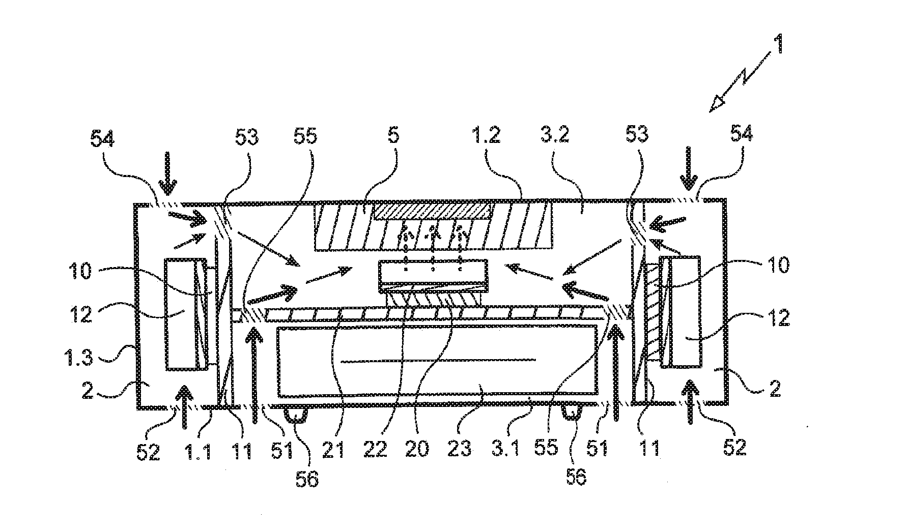
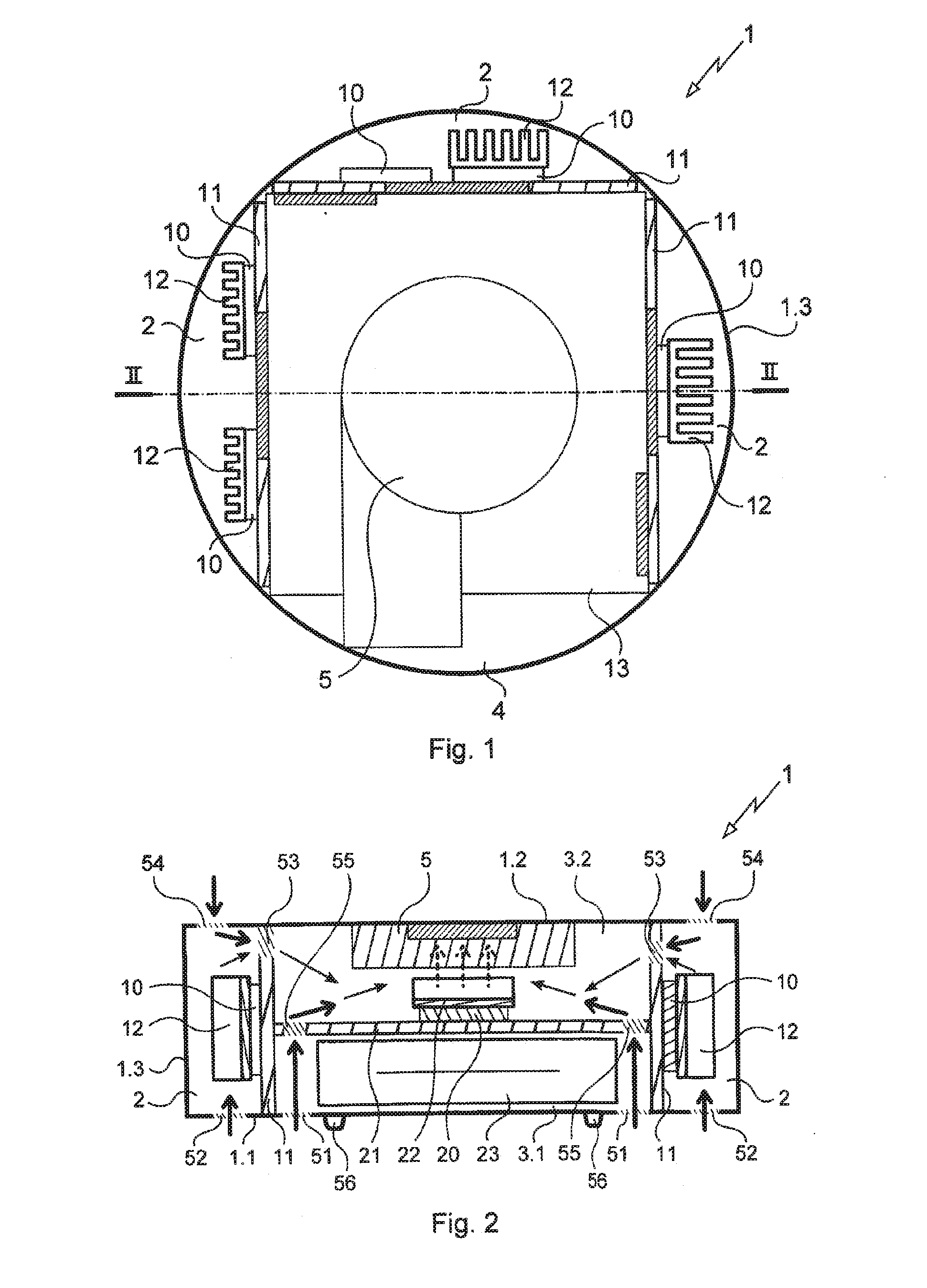
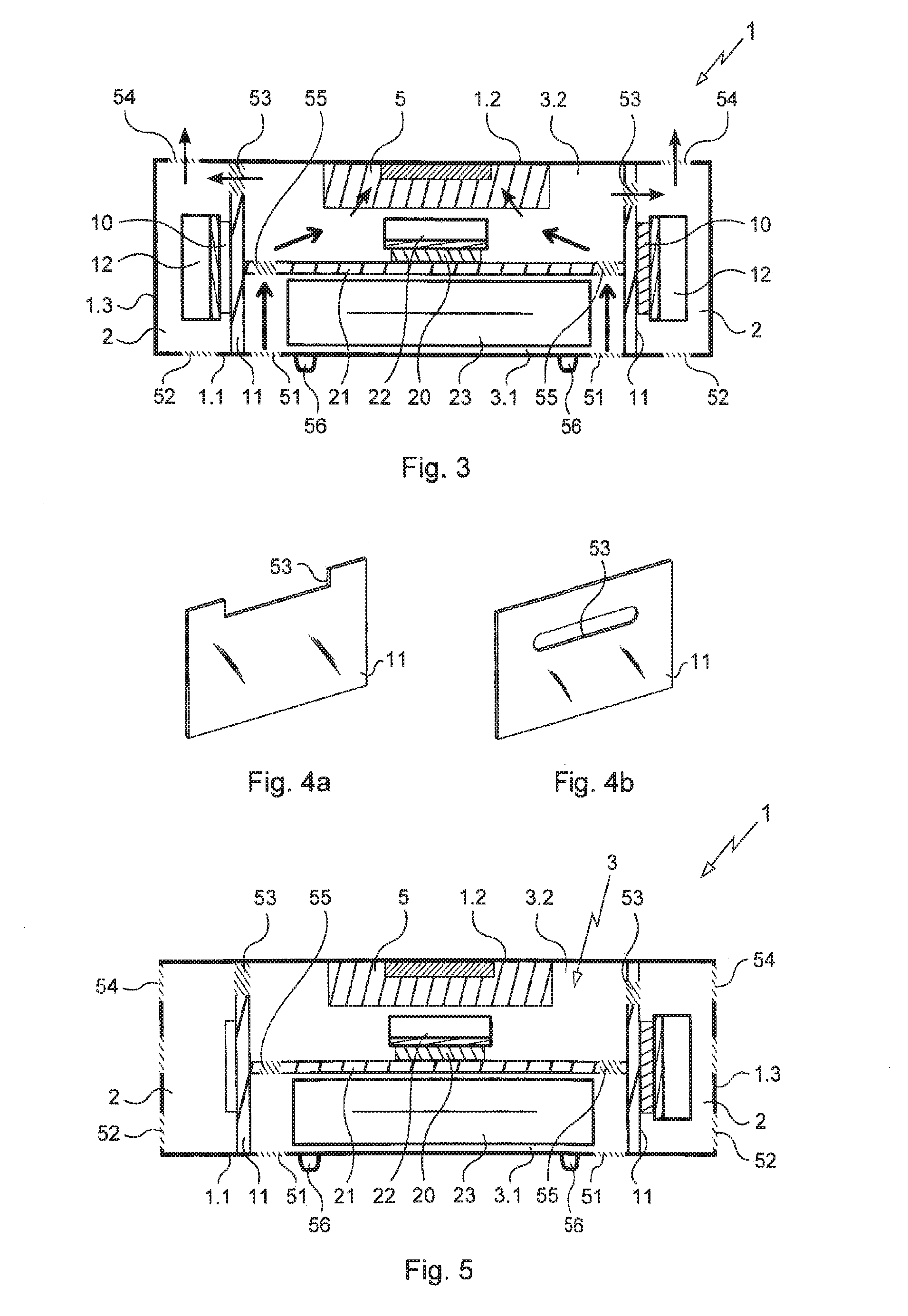
[0025]With reference to FIGS. 1 to 4, the electronic equipment comprises a box, given overall reference 1, having a bottom wall 1.1, a top wall 1.2, and a peripheral wall 1.3 extending between the bottom and top walls 1.1 and 1.2 in order to define an enclosure.

[0026]The enclosure receives electronic components, in particular electronic components 10 carried on three printed circuit plates 11 that extend vertically between the bottom and top walls 1.1 and 1.2 in order to form partitions defining within the enclosure three peripheral chambers 2 surrounding a central chamber 3 that is substantially square in shape. The electronic components 10 lie on the sides of the printed circuit plates 11 facing towards the peripheral chambers 2, and in this example some of the components 10 are provided with respective radiators 12. A vertical wall 13 extends vertical...


PUM


Abstract

Electronic equipment comprising a casing provided with lower and upper ventilation openings and with a forced-ventilation fan having an inlet in communication with the inside of the casing and an outlet opening to the outside of the casing. At least one internal partition delimits at least a peripheral chamber and a central chamber toward the top of which the fan is mounted. The openings are arranged to create a natural ventilation flow from the lower openings to the upper openings when the fan is not running and a forced-ventilation flow from the lower openings and the upper openings as far as the fan when the fan is running.

Description

BACKGROUND OF THE INVENTION[0001]1. Field of the Invention[0002]The present invention relates to electronic equipment for home or professional use such as, for example: an Internet gateway, multimedia equipment, etc.[0003]2. Brief Discussion of the Related Art[0004]Such equipment generally comprises a box containing electronic components that are to be connected to an electrical voltage source. In operation, most electrical components heat up and it is necessary to provide cooling means for preventing the temperature inside the box rising to such an extent as to become incompatible with correct operation of the equipment.[0005]For equipment in which the electronic components heat little or withstand high temperatures, bottom and top openings are provided in the box so as to enable a stream of air to be formed within the box by convection, which stream flows naturally between the bottom and top openings. Natural ventilation is advantageous because of its silence, but it suffers from ...

Claims


Application Information

Patent Timeline
IPC IPC(8): H05K7/20H05K1/02
CPCH05K7/20145H05K1/0203H05K7/20127H05K7/20136
Inventor DANGY-CAYE, NICOLAS
Owner SAGEMCOM BROADBAND
Why Eureka
Try Eureka