Imaging method and apparatus

a technology of image capture and method, applied in the direction of vehicle position/course/altitude control, process and machine control, instruments, etc., can solve the problems of high bandwidth communication between manual control of a uav and the transmission of data gathered by that uav, and achieve the effect of reducing the uncertainty of geolocation of captured image points and ensuring the manpower of the aircra

Active Publication Date: 2016-10-20
BAE SYSTEMS PLC
View PDF7 Cites 9 Cited by
  • Summary
  • Abstract
  • Description
  • Claims
  • Application Information

AI Technical Summary

Benefits of technology

[0006]In a first aspect, the present invention provides an imaging method for imaging an area of terrain using a movably sensor mounted on an unmanned aircraft, the method comprising: acquiring, by one or more processors, a specification of possible positions and orientations relative to the aircraft to which the sensor may be moved; acquiring, by the one or more processors, positional information of the area of terrain; acquiring, by the one or more processors, a specification of the maneuverability of the aircraft; using the acquired specification of the possible positions and orientations of the sensor relative to the aircraft, the acquired positional information of the area of terrain, and the acquired specification of the maneuverability of the aircraft, determining, by the one or more processors, a first procedure and a second procedure; performing, by the aircraft, the first procedure, the first procedure comprising the aircraft moving with respect to the area of terrain along a first route and the sensor moving with respect to the aircraft such that, for each point in the area of terrain, that point is coincident with a footprint of the sensor on the ground for at least some time during the first procedure; whilst the

Problems solved by technology

However, the manual control of a UAV and the transmission of data gather

Method used


Image

  • Imaging method and apparatus
  • Imaging method and apparatus
  • Imaging method and apparatus

Examples


first embodiment

[0085]the imaging process is described in more detail later below with reference to FIGS. 6 and 7.

second embodiment

[0086]the imaging process is described in more detail later below with reference to FIGS. 8 and 9.

third embodiment

[0087]the imaging process is described in more detail later below with reference to FIGS. 10 and 11.

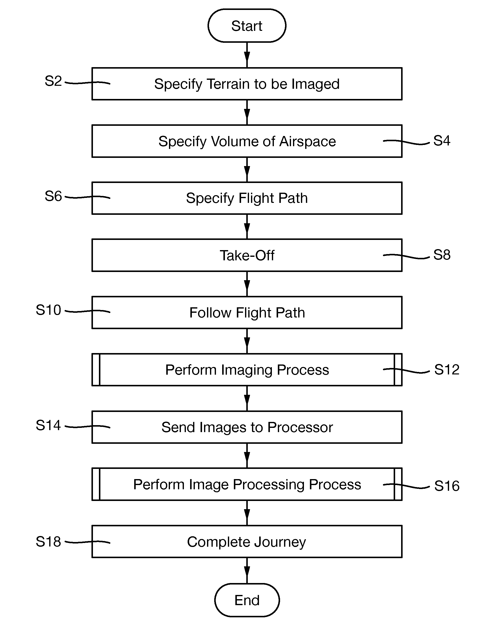
[0088]At step s14, the sensor module 10 sends the captured images to the processor 12.

[0089]At step s16 the processor 12 performs an image processing method on the received images.

[0090]An embodiment of an image processing method is described in more detail later below with reference to FIG. 12.

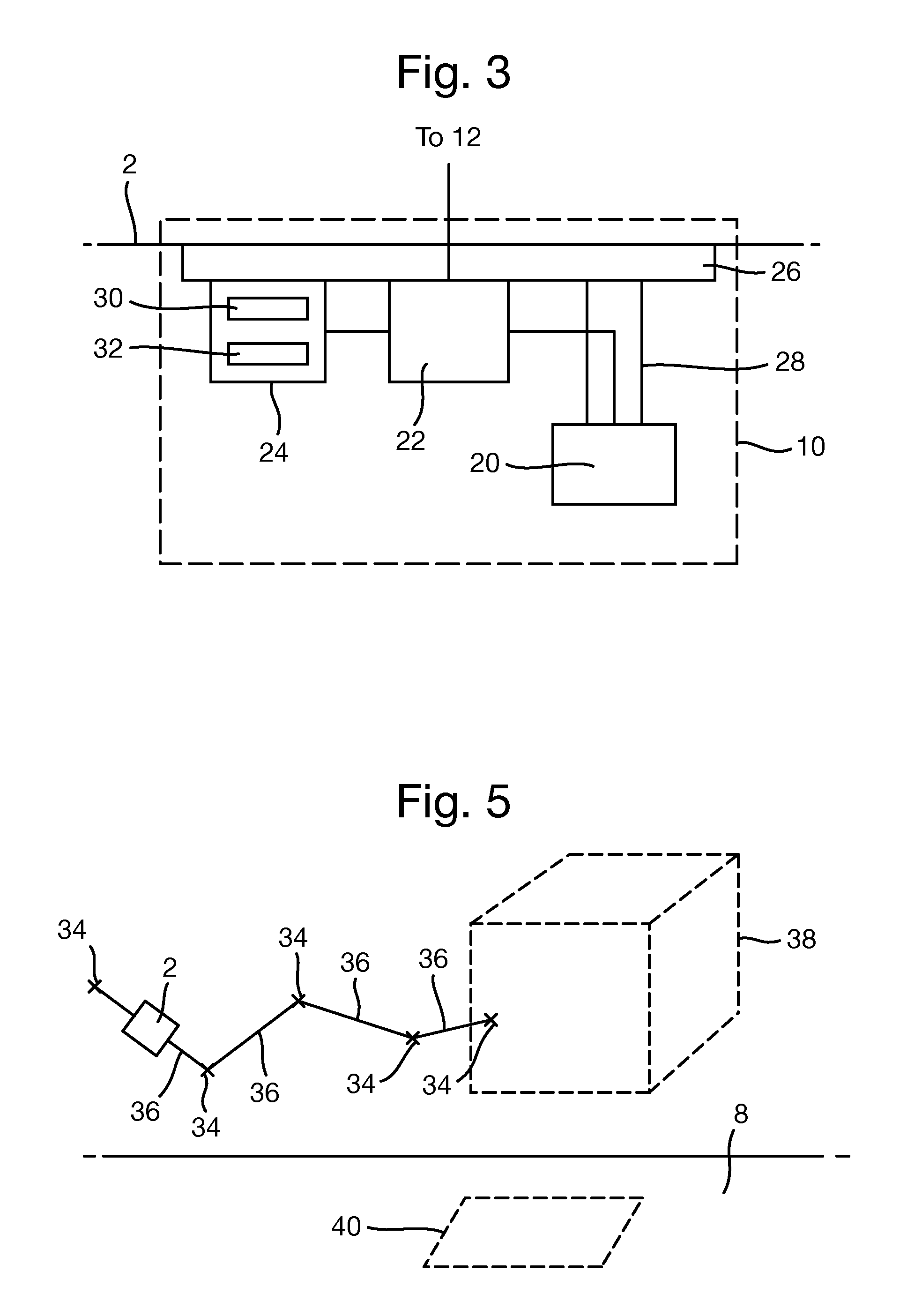
[0091]At step s18, the aircraft 2 completes its journey, for example, by returning to its launch-site (e.g. the ground station 4), for example, by following the flight path 36.

[0092]Thus, a process in which an imaging process is performed is provided.

[0093]What will now be described is a first embodiment of an imaging process performed at step s12.

[0094]In this first embodiment, the imaging target 40 is a relatively large defined area of terrain. In the first embodiment, the imaging of the imaging target 40 comprises conducting a “wide area search” of the imaging target 40. The terminology “wid...


PUM


Abstract

Disclosed is an imaging method for imaging terrain using a sensor on an unmanned aircraft. The method comprises: acquiring a range of motion of the sensor; acquiring positional information of the terrain; acquiring parameter values relating to aircraft maneuverability; using the acquired information, determining a procedure; performing, by the aircraft, the procedure and simultaneously capturing, by the sensor, a set of images of only parts of the terrain. The procedure comprises the aircraft moving with respect to the area of terrain and the sensor moving with respect to the aircraft such that each point in the area of terrain is coincident with a footprint of the sensor on the ground for at least some time. Also, every point in the area of terrain is present within at least one of the captured images.

Description

FIELD OF THE INVENTION[0001]The present invention relates to imaging large areas of terrain using sensors mounted on unmanned aircraft.BACKGROUND[0002]Unmanned Air Vehicles (UAVs) are commonly used to perform a variety of tasks. Such tasks include performing wide area searches of areas, surveillance operations, delivery of payloads, etc.[0003]Conventionally, procedures to be performed by a UAV in order to complete a task are determined by a human operator and typically involve the direct control, by the human operator, of the UAV and on-board sensors. Such procedures may include, for example, the remote flying of the UAV by the operator to follow a route, and / or the moving of on-board sensors etc.[0004]Furthermore, typically data gathered by a UAV (e.g. using on-board sensor systems) is transmitted to an entity remote from the UAV for analysis.[0005]However, the manual control of a UAV and the transmission of data gathered by that UAV tend to require relatively high band-width commu...

Claims


Application Information

Patent Timeline
IPC IPC(8): G05D1/00G08G5/00B64C39/02
CPCG05D1/0094B64C39/024B64C2201/141G08G5/0069B64C2201/123G08G5/003B64U2101/30B64U2201/10
Inventor TEBAY, ANDREW CHRISTOPHER
Owner BAE SYSTEMS PLC
Why Eureka
Try Eureka