Method of three-dimensionally measuring object surfaces

a three-dimensional measurement and object technology, applied in the field of three-dimensional measurement of object surfaces, can solve the problems of affecting the accuracy of the measurement, so as to achieve the effect of low degree of uncertainty of measurement and high resolution

Inactive Publication Date: 2003-04-01
MICHAELIS BERND +1
View PDF5 Cites 60 Cited by
  • Summary
  • Abstract
  • Description
  • Claims
  • Application Information

AI Technical Summary

Benefits of technology

Because of its local resolution and the low degree of uncertainty of measurements made possible by it, the measuring method in accordance with the invention is particularly suited for measuring vehicle bodies or parts thereof.
In contrast to known measuring methods, measurements of high resolution may be obtained by practicing the method of the invention, and when determining a measuring point value it is possible in a simple manner to ensure that the measuring points are provided equidistantly in the object coordinate system. This is deemed to be a significant advantage over the method disclosed by German patent specification DE 196 23 172.

Problems solved by technology

However, measuring coordinates in this manner suffers from a disadvantage inherent in the phase-shift method, i.e. the need for calibrating the pattern projector.
In general it is, however, more difficult or complex to calibrate a projector than it is to calibrate a camera.
Moreover, the distortion parameters are generally larger and cannot be as easily determined as in the case of a camera.
This, in turn, may result in a greater uncertainty in the calculation of the spatial coordinates.
A further problem arises from the fact that oftentimes the grey scale gradation of the stripes is not sinusoidal in a way which may be considered to be ideal.
Any such deviations may have a direct distorting effect on the results of the measurement and lead to a lower accuracy of the measurements.
Yet where only one pair of images is used, measurements may become critical at or near strong curvatures or other irregularities in the object surface.
Accordingly, the accuracy of measurements obtained by this method is strongly dependent upon the size of the measured surface and critical surfaces, i.e. strongly curved or highly irregular surfaces generally cause systematic measurement errors.
While this disadvantage could be lowered by reducing the size of the measurement surface, it would result in a reduced number of pixels for analyzing the grey scale gradation and, therefore, in a less exact position of the corresponding points determined by an analysis of the similarities.
Accordingly, seeking to solve the problem in this manner would seem at best to be of limited usefulness.
The method suffers from the drawback that it is not possible within the coordinate system of the object to measure either equidistantly or along predetermined directional vectors within the object coordinate system.

Method used


Image

  • Method of three-dimensionally measuring object surfaces

Examples


example 2

Approximation of the Surface by an Approximation Point Based Upon a Directional Vector.

In certain applications it is desirable to perform the iterative 3D measurement vertically relative to the expected surface of the measured object or in a predetermined defined direction within space (FIG. 7). The reason for it usually is the result of routines for the further processing of the "cloud" of 3D points in which data measured in this fashion is required for further processing.

To realize this requirement, iterative shifting of the approximation point is performed along a straight line in space, the position of which may be vectorially defined (FIG. 6). To this end the so-called point-direction-form may be used:

X=X.sub.0 +t.multidot..DELTA.X

Y=Y.sub.0 +t.multidot..DELTA.Y

Z=Z.sub.0 +t.multidot..DELTA.Z

wherein:

X Y, Z are coordinates of a point on a straight line in space

t; parameter for determining the point on the straight line in space

X.sub.0, Y.sub.0, Z.sub.0 are coordinates of the base ...

example 1

projection of the spatial point onto both sensor surfaces;

associating the grey value sequence to the projection points p' and p" (FIG. 7);

search for the correlation maximum by a gradient slope process.

However, in a directionally based measurement the parameter t forms the basis of the iterative approximation. Changing this parameter causes the approximation point to shift along the set straight line in space. This is a broadening of the method limited to a measurement vertically of the XY plane of the spatial coordinate system. It makes possible iteratively to determine, in a manner similar to the gradient slope process (as in Example 1), the point which may be interpreted as the point at which the straight spatial line penetrates through the surface of the measured object. Example 3

Approximation of the Surface by 3.times.3 Spatial Points

In this example 3.times.3 spatial points are used for approximating the surface. The reason for doing it is the desire to decrease the statistical ...


PUM


Abstract

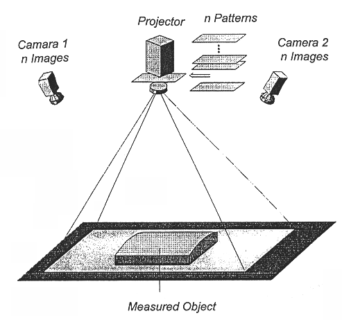
A method of optically measuring a three-dimensional surface by sequentially projecting predetermined patterns onto the surface to generate thereon a predetermined number of temporary images of different intensities. Each of the images is recorded by sensors of at least two matrix cameras and grey values are determined in a pixel by pixel manner of those images. A first approximation value is determined for calculating a first measuring point on the surface, and coordinates of this approximation value are associated on the sensor surfaces of both camera. The grey values of the images of each camera at the positions of the projected points are determined by subpixel interpolation, and a pair of grey scale gradation is detected therefrom. These steps may be repeated until a measuring point is determined by a pair of grey scale gradations analyzed to be similar.

Description

1. Field of the InventionThe invention, in general, relates to a method of taking three-dimensional measurements of an object surface and, more particularly, to a method of projecting patterns onto an object surface and of defining the object coordinates by analyzing the similarity of the grey scale gradation in images of the object surface taken by at least two matrix cameras.2. The Prior ArtMethods heretofore known of optically measuring three-dimensional objects at close range are, for instance, photogrammetric methods or stripe-projection methods. Whereas in the stripe-projection method striped patterns which are geometrically as exact as possible are projected onto the object to be measured, the patterns used in photogrammetric methods may be more or less arbitrary.The projector for projecting patterns onto an object surface will hereinafter sometimes be referred to a pattern projector. The device for generating an image of the object surface and the sensor for recording the in...

Claims


Application Information

Patent Timeline
Patent Type & Authority Patents(United States)
IPC IPC(8): G06T7/00G07F17/00G07F17/16H04M15/00H04M3/493H04M3/487H04M7/00G01B11/24G01B11/25G06T7/521G06T7/593
CPCG01B11/2518G06T7/0075G06T7/0057G06T2207/30164G06T7/521G06T7/593
Inventor MICHAELIS, BERNDALBRECHT, PETER
Owner MICHAELIS BERND
Why Eureka
Try Eureka