Accommodating intraocular lens

Active Publication Date: 2016-10-27
MIRAI EYE INC
View PDF7 Cites 14 Cited by
  • Summary
  • Abstract
  • Description
  • Claims
  • Application Information

AI Technical Summary

Benefits of technology

[0021]Moreover, when the front supporting portion is formed in an open state like a ring form, hydatoid flows from an anterior capsule incision portion to the space between the front supporting portion and the connecting portion and flows into the lens capsule, and the lens equator is exposed to the hydatoid. Thus, the growth or fibroplasia of the lens epithelial cells in the lens equator is suppressed and the occurrence of the secondary cataract can be prevented.
[0022]Further, when the front supporting portion and the rear supporting portion move in the direction closer to or away from each other according to the movement of the lens capsule, force is applied directly or indirectly from the connecting portion according to the movement of the connecting portion and the curvature of the optical portion changes. Thus, it is possible to exert the focus accommodation power with high accuracy and sufficiently.
[0043]According to the present invention, due to the bia

Problems solved by technology

On the other hand, it is also known that, since the contents of the lens and the lens capsule become hardened in old ages and lose flexibility, thus making the thickness of the lens rarely change, the ability (hereinafter referred to as accommodation power) to accommodate the focus range freely from distance vision to near vision is lost (this is referred to as presbyopia).
However, since the monofocal lenses are generally formed of a material such as polymethylmethacrylate (PMMA), silicon,

Method used


Image

  • Accommodating intraocular lens
  • Accommodating intraocular lens
  • Accommodating intraocular lens

Examples


first embodiment

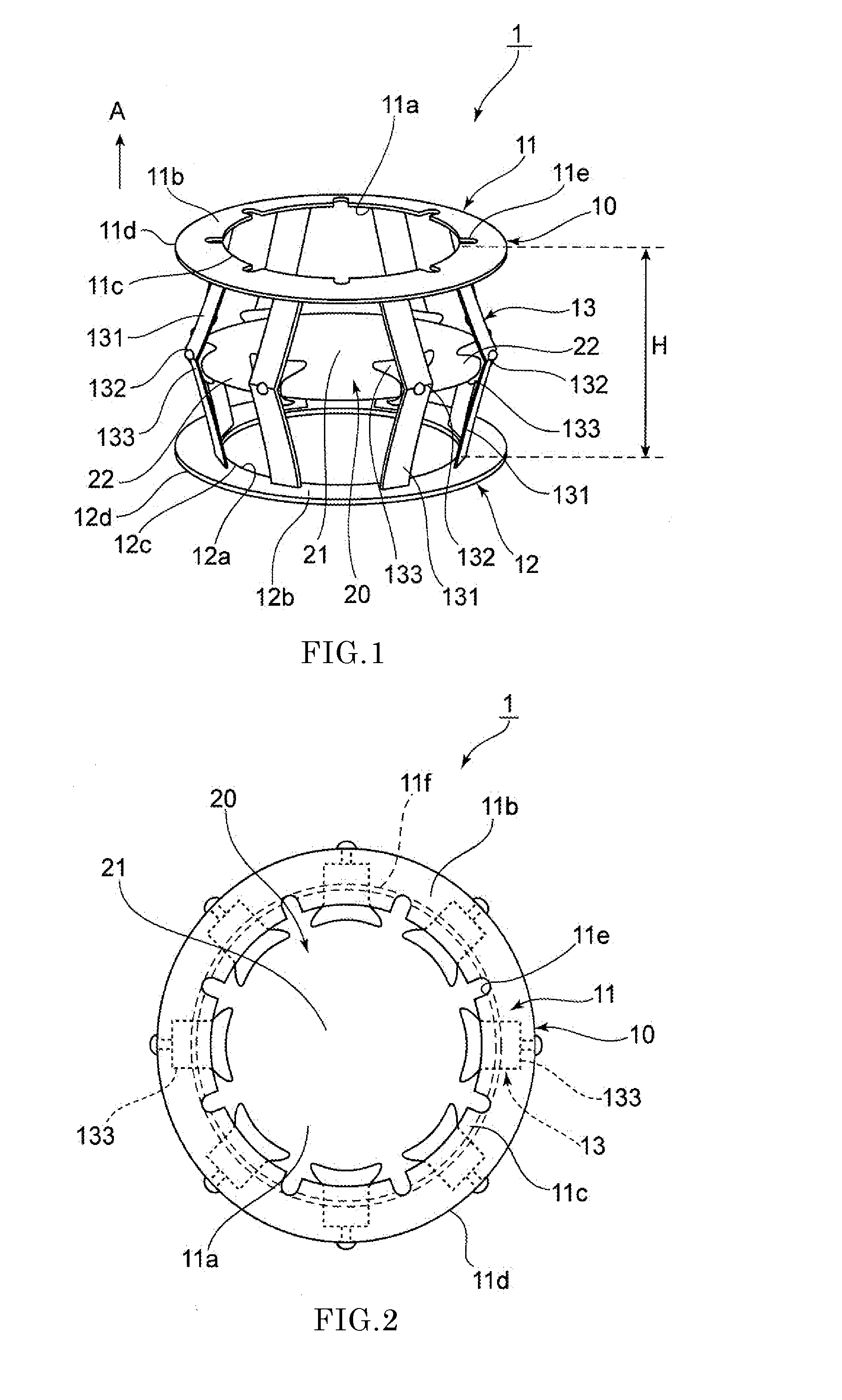
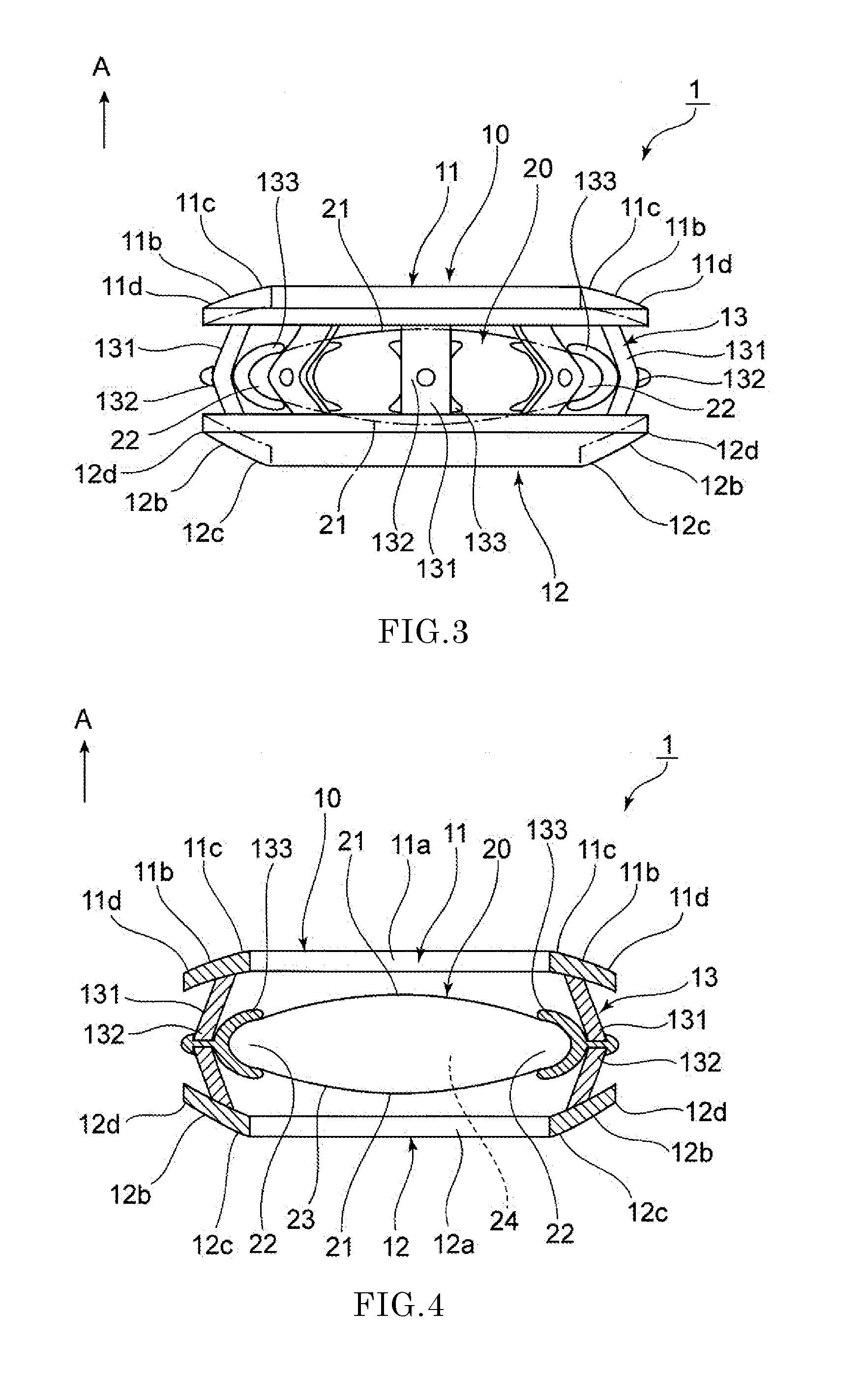
[0064]Next, a first embodiment of an accommodating intraocular lens according to the present invention will be described with reference to FIGS. 1 to 5.

[0065]An accommodating intraocular lens 1 includes a lens capsule expanding device (hereinafter referred to as a device 10) and an optical portion 20 disposed inside the device 10. In the following description, the direction indicated by arrow A illustrated in the drawings is defined as a front side and the opposite direction is defined as a rear side.

[Device Configuration]

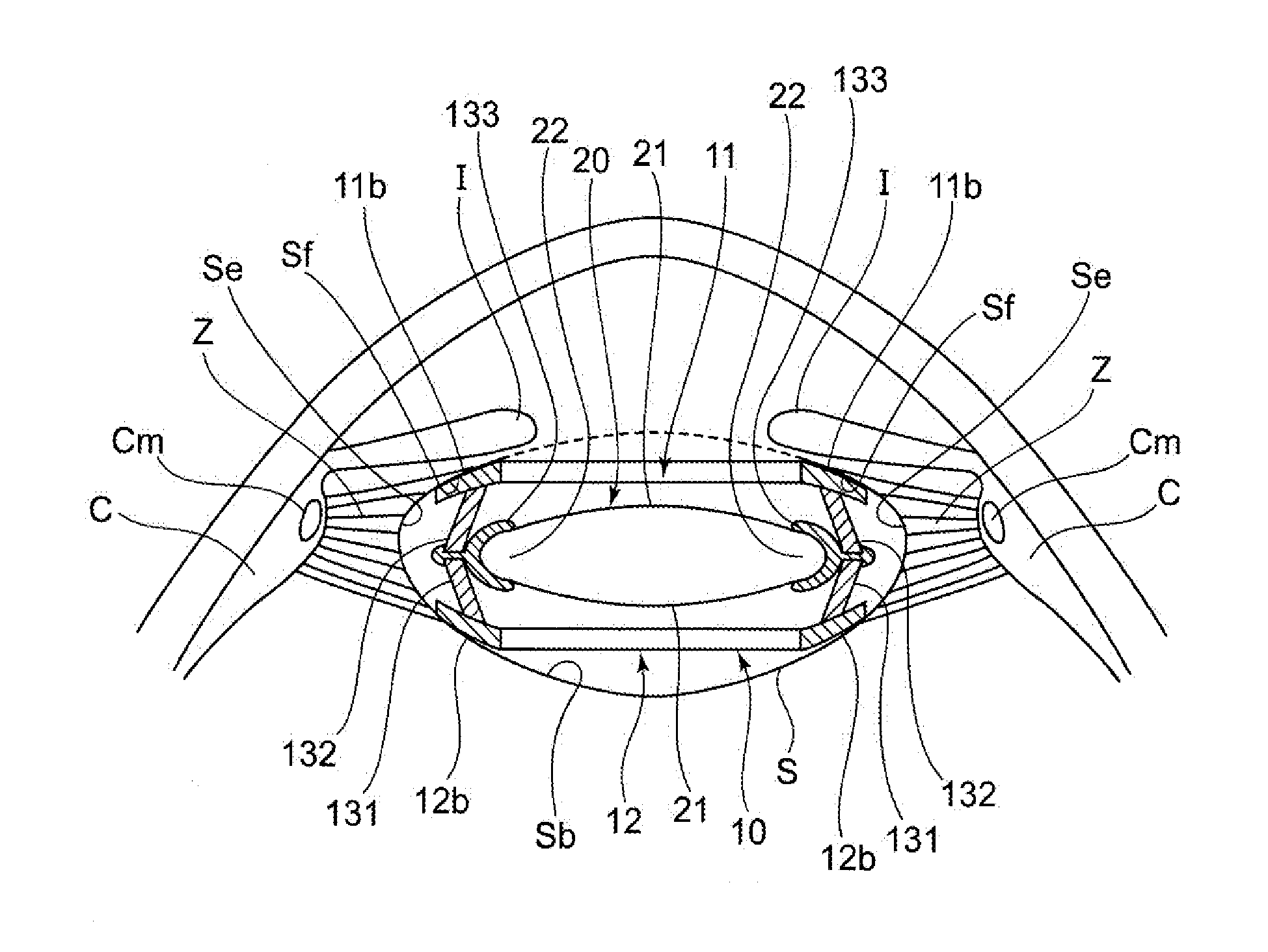
[0066]As illustrated in FIG. 5, the device 10 is arranged in the lens capsule S of which the anterior capsule Sf is incised during ophthalmic surgeries such as an extracapsular extraction surgery performed as a part of a cataract surgery, a refractive correction surgery, or a presbyopia correction surgery. As illustrated in FIG. 1, the device 10 includes a front supporting portion 11 positioned on the front side in the lens capsule S, a rear supporting portion 12 p...

second embodiment

[0096]Next, a second embodiment of the accommodating intraocular lens 1 according to the present invention will be described with reference to FIG. 6. In the following description, only constituent elements different from those of the above-described embodiment will be described and the same constituent elements as those of the above-described embodiment will be denoted by the same reference numerals and the description thereof will be omitted.

[0097]In the device 10 according to the present embodiment, as illustrated in FIG. 6, the locking member 133 is not provided, and the circumferential portion 22 of the optical portion 20 is directly locked to the inner side of the connecting pieces 131.

[0098]Thus, as illustrated in FIG. 6 (a), during distance vision (non-focus accommodation), the front supporting portion 11 and the rear supporting portion 12 move in the direction closer to each other and the degree of expansion of the connecting portion 13 in the radially outward direction inc...

third embodiment

[0100]Next, a third embodiment of the accommodating intraocular lens 1 according to the present invention will be described with reference to FIG. 7.

[0101]As illustrated in FIG. 7, the locking member 133 according to the present embodiment has a bulging portion 133a which is formed on the inner side of a front end and a rear end.

[0102]Thus, as illustrated in FIG. 7 (a), during distance vision (non-focus accommodation), the front supporting portion 11 and the rear supporting portion 12 move in the direction closer to each other and the degree of expansion of the connecting portion 13 in the radially outward direction increases. As a result, the facing connecting pieces 131 move in the direction away from each other and the distance between the connecting pieces 131 increases. Therefore, the optical portion 20 does not receive force in the radially inward direction from the connecting pieces 131 of the connecting portion 13 and is relaxed up to the original shape whereby the curvature...


PUM


Abstract

An intraocular lens includes a lens capsule expanding device and an optical portion. The lens capsule expanding device includes a front supporting portion to make contact with an inner surface of an anterior capsule. A rear supporting portion provided on a rear side of the front supporting portion makes contact with an inner surface of a posterior capsule while facing the front supporting portion. A connecting portion connects the front supporting portion and the rear supporting portion so as to have biasing force in a direction of separating the front supporting portion and the rear supporting portion from each other. Due to the biasing force, the front supporting portion presses the inner surface of the anterior capsule and the rear supporting portion presses the inner surface of the posterior capsule. The optical portion changes the curvature of a central portion according to movement of the connecting portion.

Description

TECHNICAL FIELD[0001]The present invention relates to an accommodating intraocular lens which is inserted into a lens capsule of which the anterior capsule is incised during ophthalmic surgeries such as an extracapsular extraction surgery performed as a part of a cataract surgery, a refractive correction surgery, or a presbyopia correction surgery.BACKGROUND ART[0002]Generally, the focus accommodation of the human eyes (hereinafter simply referred to as “accommodation”) is realized by changing the thickness of the lens. As illustrated in FIG. 18, a lens L is a convex transparent member having a diameter of approximately 9 to 10 mm and a thickness of approximately 4 to 5 mm and exerting a lens function, and is fixed to a ciliary body C by Zinn's zonules Z in such a manner as to be arranged on the rear side of the iris I in a state of being encapsulated by a lens capsule S.[0003]A detailed accommodation mechanism will be described. For example, when a person looks at a distant object,...

Claims


Application Information

Patent Timeline
IPC IPC(8): A61F2/16
CPCA61F2/1635A61F2/16015A61F2250/0003A61F2/1648A61F2/1694
Inventor AKURA, JUNSUKE
Owner MIRAI EYE INC
Why Eureka
Try Eureka