Heat exchanger with improved flow

a technology of heat exchanger and flow, which is applied in the direction of indirect heat exchanger, laminated elements, lighting and heating apparatus, etc., can solve the problem of light maldistribution of fluids to exchange heat, and achieve the effect of increasing the strength of the heat exchanger

Active Publication Date: 2016-10-27
SWEP INT
View PDF57 Cites 6 Cited by
  • Summary
  • Abstract
  • Description
  • Claims
  • Application Information

AI Technical Summary

Benefits of technology

[0010]In one embodiment of the invention, said dents are placed such that contact points between said ridges and grooves of the neighbouring plates in the stack are not affected by said dents. This increases the strength of the heat exchanger.
[0011]If not enough effect on the flow distribution is achieved by the arrangement above, dents may be provided around two neighboring port openings, wherein the dents in the vicinity of one of said neighboring port openings are placed in the ridges, and the dents in the vicinity of the other of the two neighboring port openings are placed in the grooves.

Problems solved by technology

As well known by persons skilled in the art of heat exchangers, heat exchangers of the type described above have one small drawback compared to heat exchangers made from non-identical plates, namely that inlet and outlet port openings for one of the fluids are placed on one side of the axis of the heat exchanger, whereas the openings for the other fluid are place placed on the other side of the axis.
This leads to a slight maldistribution of the fluids to exchange heat, since there is a shorter way (and hence less resistance) for the fluids to travel in a straight line from port opening to port opening.

Method used


Image

  • Heat exchanger with improved flow
  • Heat exchanger with improved flow
  • Heat exchanger with improved flow

Examples


Embodiment Construction

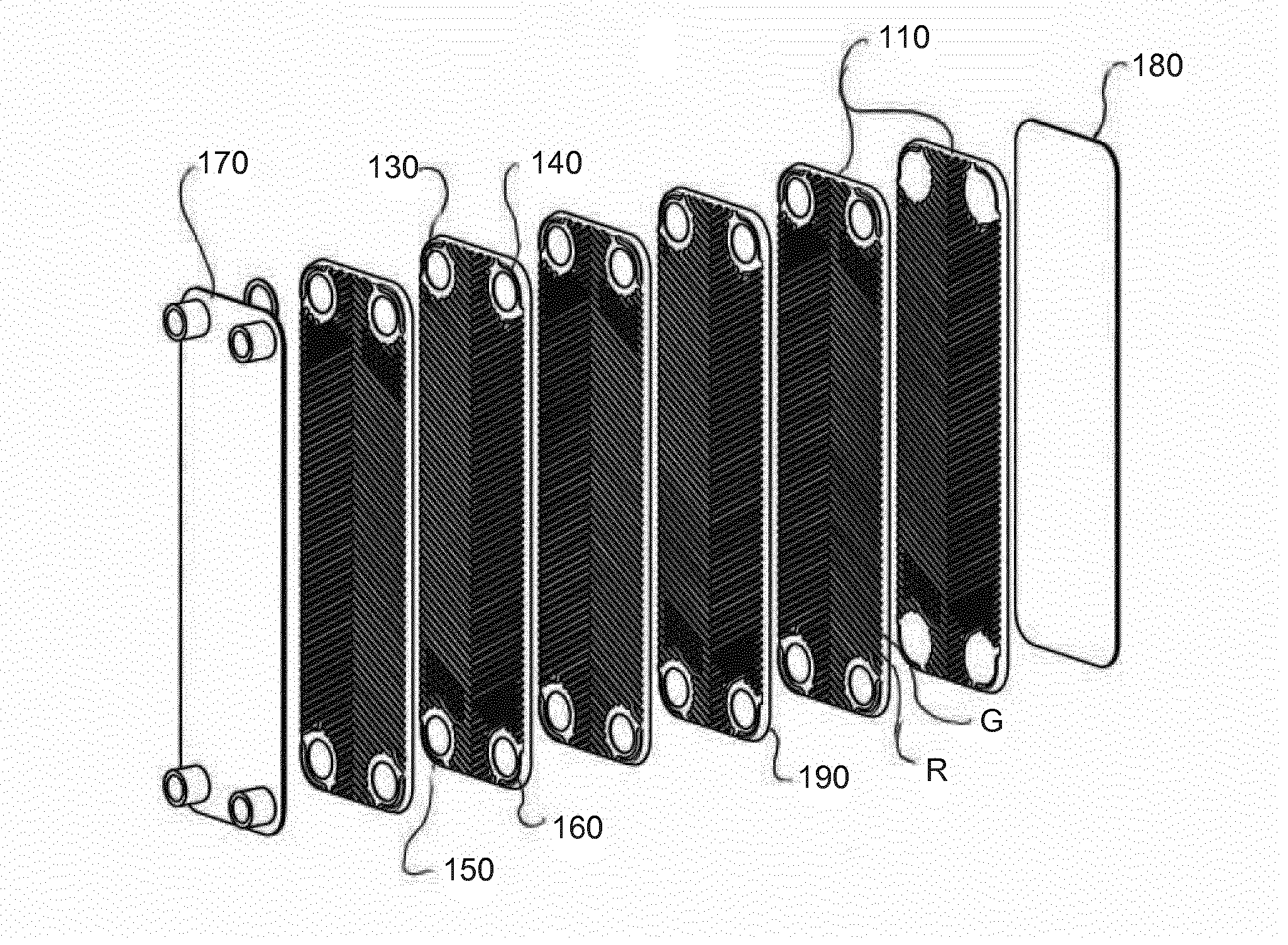
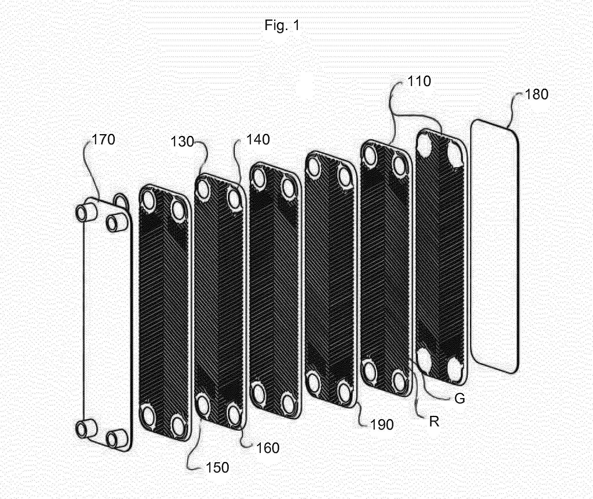
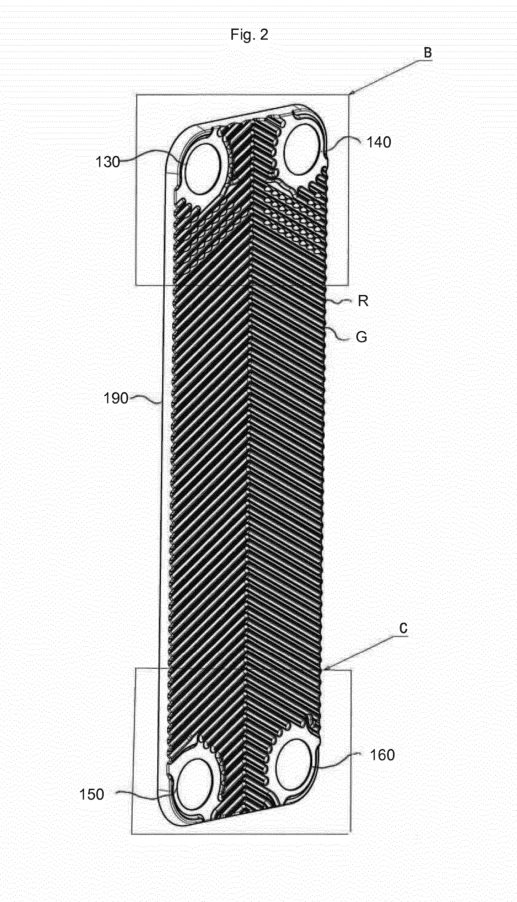
[0017]With reference to FIG. 1, a heat exchanger 100 according to the present invention comprises a number of identical heat exchanger plates 110, each comprising four port openings 130, 140, 150 and 160, the openings 130, 150 being inlet openings and outlet openings, respectively, for a first fluid, the openings 160, 140 being inlet openings and outlet openings, respectively, for a second fluid intended to exchange heat with the first fluid.

[0018]The plates also comprise ridges R and grooves G arranged in a herringbone pattern and adapted to keep the plates on a distance from one another under formation of flow channels. Areas around the port openings are arranged on different heights in order to allow for selective fluid flow to the flow channels. The areas around the port openings 130 and 150 are provided on the same height, e.g. the height of the ridges R, whereas the areas around the port openings 140, 150 are provided on another height, e.g. the height of the grooves G.

[0019]T...


PUM


Abstract

A heat exchanger comprises a number of identical heat exchanger plates stacked in a stack. Every other heat exchanger plate is turned 180 degrees in its plane relative to its neighboring plates, and each heat exchanger plate comprises at least four port openings and a herringbone pattern comprising pressed ridges and grooves. The ridges and grooves are adapted to keep the plates on a distance from one another under formation of flow channels, wherein areas around the port openings are arranged on different levels, such that selective flow from the port openings to the flow channels is achieved. Dents are arranged in the ridges and grooves in the vicinity of any of the port openings, said dents being arranged to increase the flow resistance to promote a more even flow distribution in said flow channel.

Description

FIELD OF THE INVENTION[0001]The present invention relates to a heat exchanger comprising a number of identical heat exchanger plates stacked in a stack, wherein every other heat exchanger plate is turned 180 degrees in its plane relative to its neighboring plates, and wherein each heat exchanger plate comprises at least four port openings and a herringbone pattern comprising pressed ridges and grooves, said ridges and grooves being adapted to keep the plates on a distance from one another under formation of flow channels, wherein areas around the port openings are arranged on different levels, such that selective flow from the port openings to the flow channels is achieved.PRIOR ART[0002]The most common type of heat exchanger is the type of heat exchangers comprising a number of identical heat exchanger plates, each comprising port openings, the surrounding areas of which being located at different heights to arrange for selective fluid communication into flow channels arranged by i...

Claims


Application Information

Patent Timeline
Patent Type & Authority Applications(United States)
IPC IPC(8): F28F3/04F28F13/08F28D9/00
CPCF28F3/046F28D9/005F28F2275/04F28F13/08F28F3/044F28F2215/10F28F9/026F28F3/086F28F3/02F28F13/06F28F2250/10F28F13/02F28F3/08F28F3/04F28F13/12F28D9/0025F28D1/0308F28F3/083F28D9/0037F28F3/10F28D9/0043F28F3/042F28D9/0031
Inventor ANDERSSON, SVEN
Owner SWEP INT
Why Eureka
Try Eureka