

Fluid encapsulated flooring system
- Summary
- Abstract
- Description
- Claims
- Application Information
AI Technical Summary
Benefits of technology
Problems solved by technology
Method used
Image

Examples
Embodiment Construction
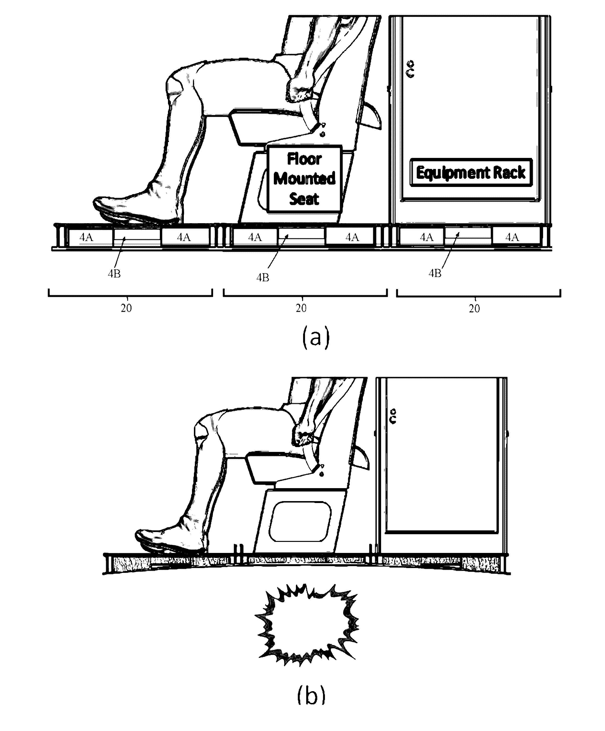
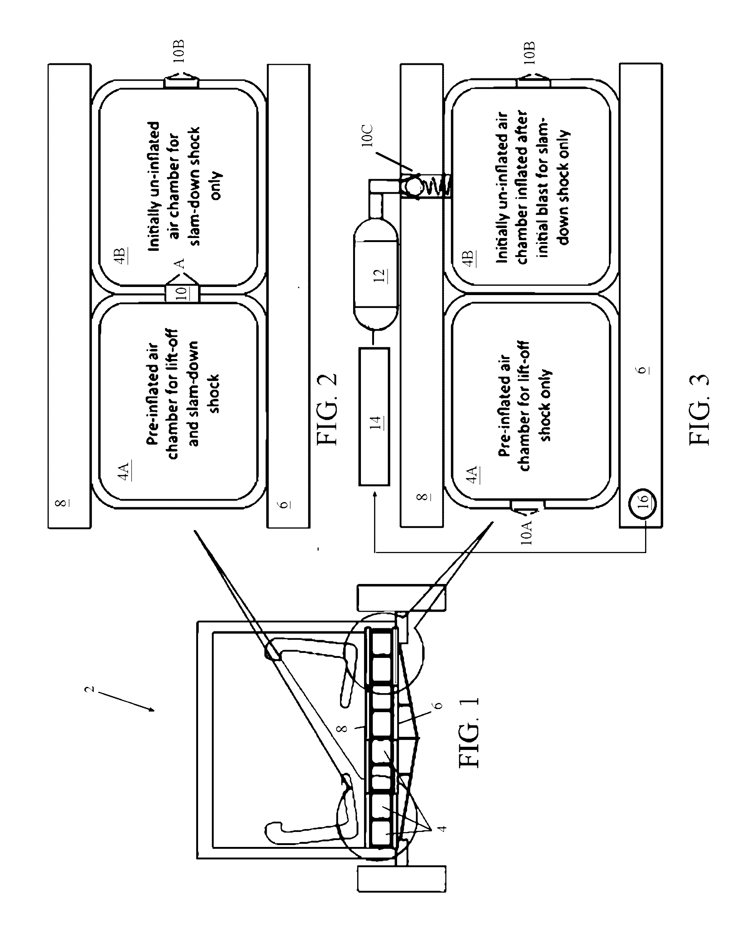
[0033]FIG. 1 depicts an embodiment of the fluid-encapsulated flooring system 2 of the invention used as vehicular flooring. The flooring system 2 generally includes a plurality of fluid chambers 4 sandwiched between a base plate 6 and an independent top plate (the “payload interface 8”). The fluid chambers 4 are inflatable, and may comprise either primary chambers (pre-inflated) or secondary (initially uninflated) chambers. The fluid-encapsulated flooring system 2 employs a sequence of valves 10 (See FIGS. 2-3) for venting and / or inflation, and the particular valve 10 (See FIGS. 2-3) and primary / secondary chamber 4 arrangements may vary slightly depending on the mode of operation.
[0034]For purposes of this description, “valve” shall mean any type of valve or orifice used to control fluid flow rate, including but not limited to a simple fixed orifice; a variable orifice; a flow regulator valve, a bypass flow regulator; a demand-compensated flow control valve; a pressure-compensated, ...
PUM
 Abstract
Description
Claims
Application Information