Optical scanning device, illumination device, projection apparatus and optical device

a technology of optical scanning and illumination, applied in the direction of projection device, picture reproducer, instrument, etc., can solve the problems of high installation cost, inability to improve the average speckle reduction effect, and large-scale optical scanning device with high installation cost, so as to reduce speckles, improve the multiplexity of angles, and finer the effect of scanning

Active Publication Date: 2016-10-27
DAI NIPPON PRINTING CO LTD
View PDF0 Cites 22 Cited by
  • Summary
  • Abstract
  • Description
  • Claims
  • Application Information

AI Technical Summary

Benefits of technology

[0005]Optical scanning devices have a MEMS mirror or the like that has a reflection surface. The reflection surface is rotated in the uniaxial or biaxial direction at a specific deflection angle to change a reflection direction of coherent light beams. The coherent light beams reflected on the reflection surface are directly or indirectly incident on an optical device. For reducing speckles, it is desirable to scan the optical device with the coherent light beams by fine scanning as much as possible. The reason is that, the finer the scanning, the

Problems solved by technology

However, in order to scan the optical device with the coherent light beams by fine scanning as much as possible, it is required to drive the reflection surface of the optical scanning device accurately at a high speed, which requires a large-scale optical scanning devi

Method used


Image

  • Optical scanning device, illumination device, projection apparatus and optical device
  • Optical scanning device, illumination device, projection apparatus and optical device
  • Optical scanning device, illumination device, projection apparatus and optical device

Examples


Embodiment Construction

[0028]Hereinafter, embodiments of the present invention will be explained in detail. In the accompanying drawings of the present specification, in order to simplify the drawings and make understanding easy, the scale, the ratio of height to width, etc., are appropriately modified or enlarged from actual ones.

[0029]Shapes and geometrical conditions, and also their degrees used in this specification are defined. For example, the terms such as “parallel”, “orthogonal” and “the same”, the values of length and angle, etc. are, not to limited to the strict sense of the terms, but interpreted to such an extent that a similar function can be expected.

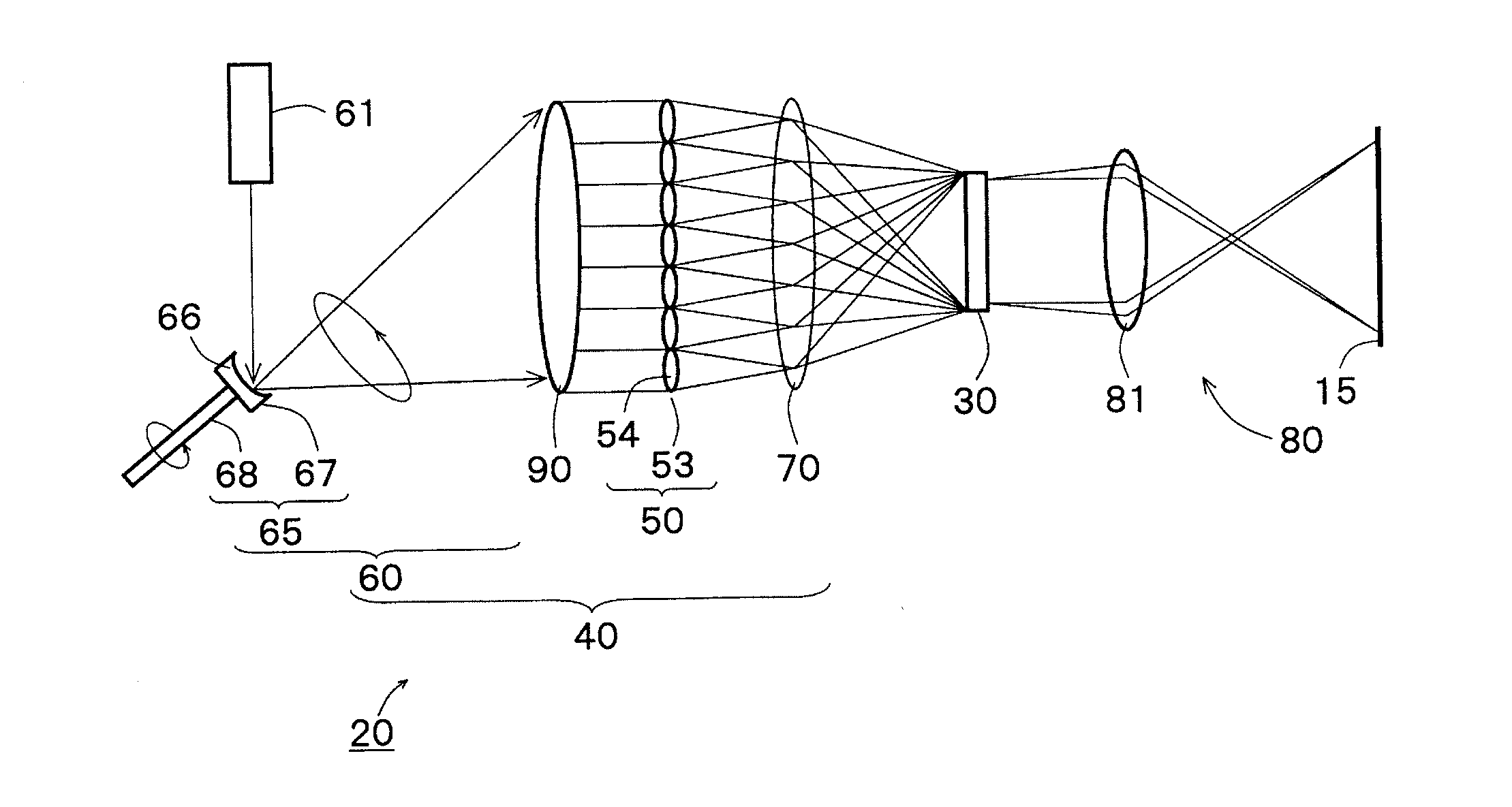
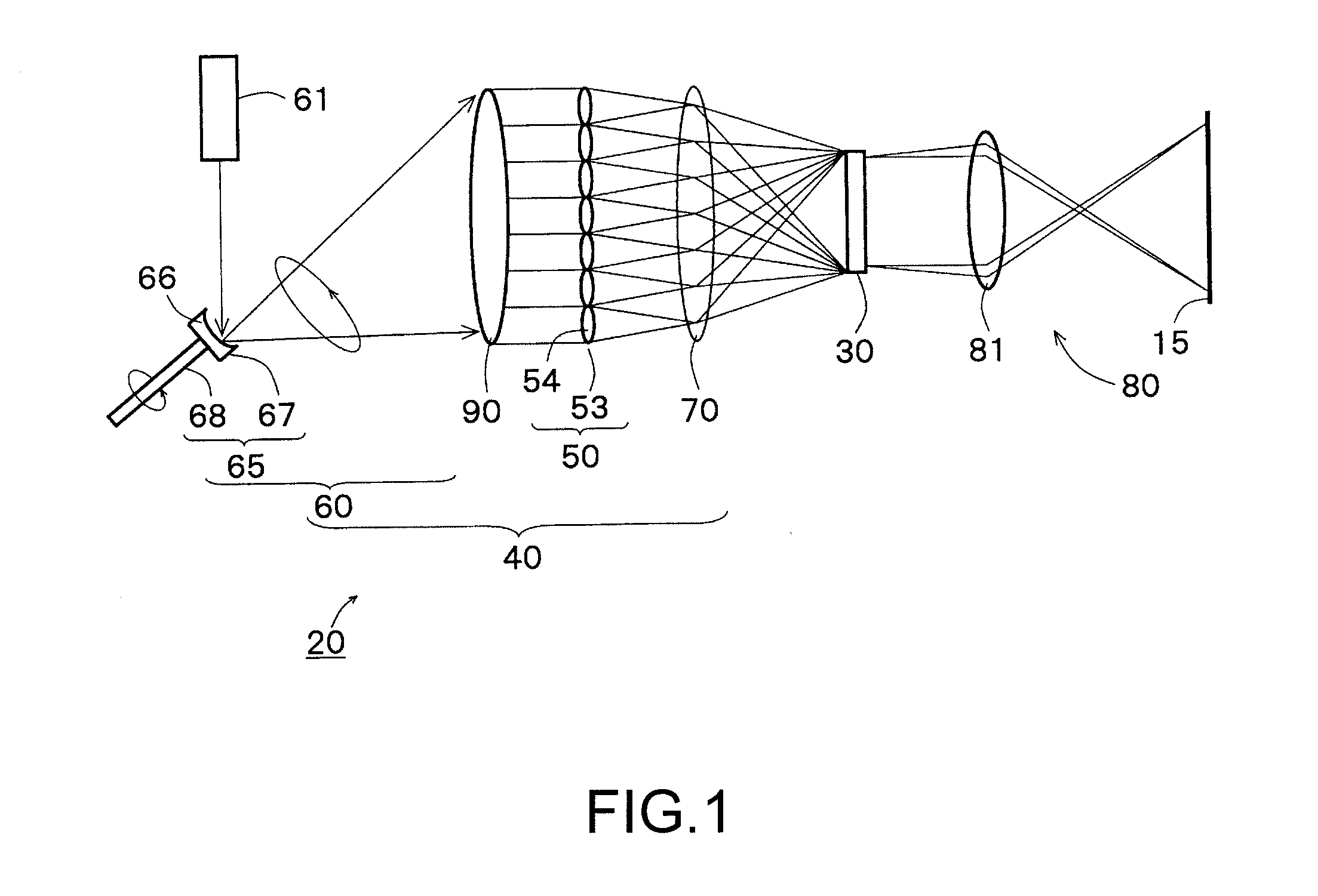
[0030]FIG. 1 is a block diagram schematically showing the configuration of a projection apparatus provided with an illumination device according to an embodiment of the present invention. The projection apparatus 20 of FIG. 1 is provided with an irradiation unit 60, a collimator lens 90, an optical device 50, a condenser lens (convergent optica...


PUM


Abstract

An illumination device includes a diffusion member having an anisotropic diffusion surface, a rotary shaft member configured to rotate the anisotropic diffusion surface while a coherent light beam from a light source is illuminated on the anisotropic diffusion surface, and an optical device that further diffuses a coherent light beam diffused on the anisotropic diffusion surface, wherein the coherent light beam diffused on the anisotropic diffusion surface is diffused in a form of line and the diffused coherent light beam in the form of line is configured to move to draw a locus of rotation in one direction in accordance with the rotation of the anisotropic diffusion surface.

Description

FIELD OF THE INVENTION[0001]The present disclosure relates to an optical scanning device, an illumination device, a projection apparatus and an optical device, which use a coherent light beam as a light source.BACKGROUND OF THE INVENTION[0002]Projection apparatuses that use a semiconductor laser as a light source have been spread under a background of high output performance and cost-down of semiconductor lasers, and improvement in performance of MEMS (Micro Electro Mechanical System) mirrors that are used to reflect a coherent light beam.[0003]However, there is a problem in that coherent beams emitted from a coherent light source cause speckles to be generated on a projection screen. Speckles are a spotted pattern which is formed when a coherent light beam such as a laser beam is illuminated on a scattering plane. If speckles are generated on a screen, they are observed as spotted luminance unevenness, i.e. brightness unevenness, thus becoming a factor of giving a physiologically a...

Claims


Application Information

Patent Timeline
IPC IPC(8): G02B27/48G02B27/09G02B27/30H04N9/31G02B5/02G02B26/10
CPCG02B27/48G02B5/0257G02B26/10G02B27/0983H04N9/3129H04N9/3161G02B27/30G02B26/105G02B27/0905G02B27/0933G02B27/0961G03B21/2033G03B21/208H04N9/3152
Inventor KURASHIGE, MAKIO
Owner DAI NIPPON PRINTING CO LTD
Why Eureka
Try Eureka