Easily openable box
- Summary
- Abstract
- Description
- Claims
- Application Information
AI Technical Summary
Benefits of technology
Problems solved by technology
Method used
Image


Examples
first embodiment
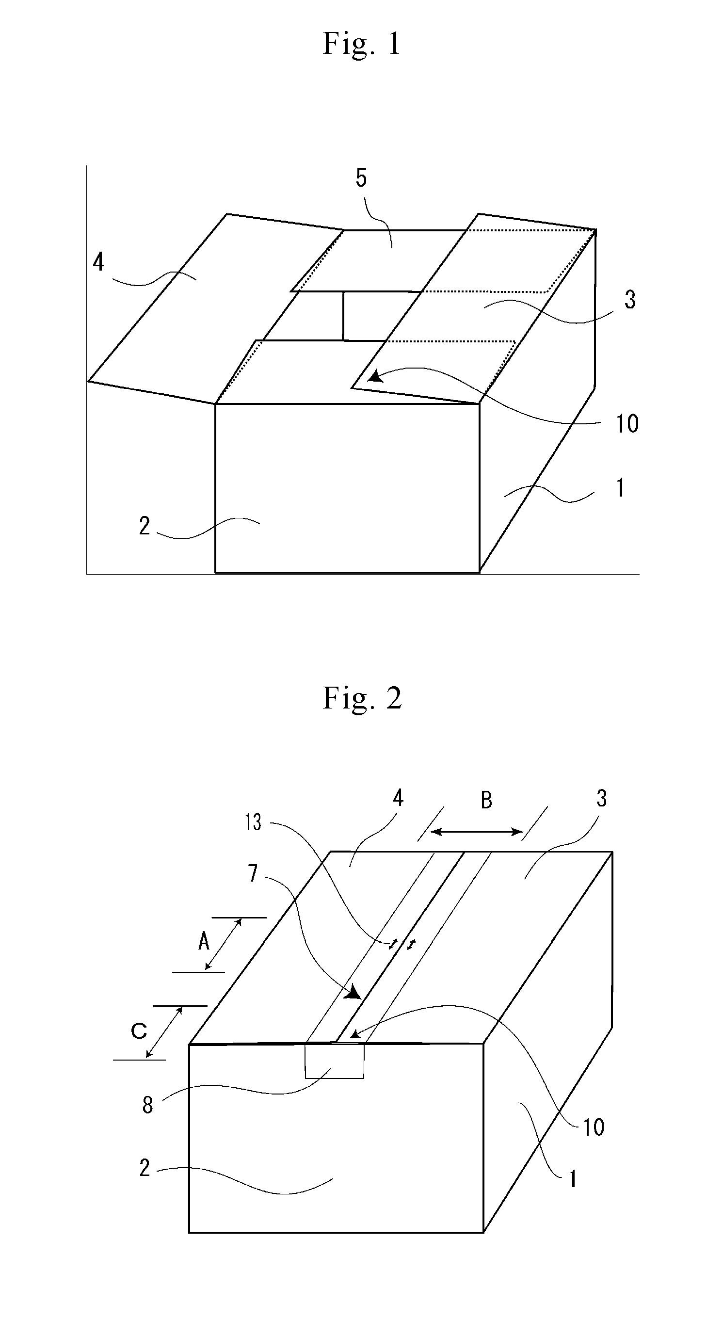
[0069]An easily openable box of the first embodiment of the present invention will be explained with reference to FIG. 2 and FIG. 3. Note that the first embodiment corresponds to claim 1.
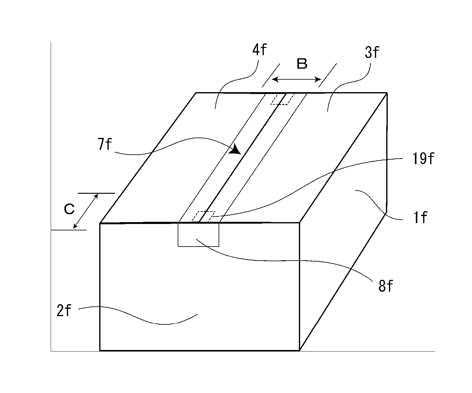
[0070]FIG. 2 is a perspective view showing a box of the first embodiment sealed by an adhesive tape 8. As shown in FIG. 2, allow marks 13 having a length of 10 mm are preliminarily printed on an approximately center of the box at a portion near the end portion of the mating portion of the outer flaps to indicate a forming position of the cut.
[0071]FIG. 3 is a plan view showing a part indicated by A-B in FIG. 2. FIG. 3 shows a state that a cut 12 to function as a trigger to unseal the adhesive tape 8 is formed on the adhesive tape 8 at a portion facing to a mating portion 7 located between two arrow marks 13 in a state that the box is sealed. In the figure, the cut is formed by using the device having needles on the roller surface shown in FIG. 21 as an example. Thus, the cut is formed on the other p...
second embodiment
[0094]An easily openable box concerning the second embodiment of the present invention will be explained with reference to FIG. 5 and FIG. 6.
[0095]In the second embodiment, a clearance is formed on the mating portion instead of the indicator of the arrow marks indicating the forming position of the cut of the first embodiment.
[0096]FIG. 5 is a plan view showing the clearance. FIG. 5 corresponds to A-B in FIG. 2 of the first embodiment.
[0097]As shown in FIG. 5, the second embodiment is characterized in that a clearance 9b having an approximately trapezoidal shape is formed at the center of the box on a mating portion 7b of the edge portions of an outer flap 3b and an outer flap 4b facing to each other. As shown in the development view of FIG. 6, a cutout 6b is formed on the edge of the mating portion side of the outer flap 3b located at an opening surface of the box to form the clearance 9b.
[0098]In FIG. 5, the width (length in a direction orthogonal to the mating portion 7b) of the...
third embodiment
[0110]The third embodiment of the present invention will be explained with reference to FIG. 7, FIG. 8 and FIG. 9. Note that the third embodiment corresponds to claim 2.
[0111]As shown in FIG. 7, the box of the third embodiment has a clearance 9c having an approximately triangular shape in a plan view. The clearance 9c is formed on a mating portion 7c between an outer flap 3c and an outer flap 4c located at an opening surface of the box, and is adjacent to an end face plate 2c.
[0112]FIG. 8 is a development view of the box of the third embodiment. As shown in the figure, the outer flaps are cut along a line connecting a first point and a second point. The first point is separate 5 mm in a direction along an edge of the end face plate side of the outer flaps from a corner of the mating portion side of each of the outer flaps located at the opening surface. The second point is separate 20 mm in a direction along an edge of the mating portion side of the outer flaps from the corner. Her...
PUM
 Abstract
Description
Claims
Application Information
 - Generate Ideas
- Intellectual Property
- Life Sciences
- Materials
- Tech Scout
- Unparalleled Data Quality
- Higher Quality Content
- 60% Fewer Hallucinations
Browse by: Latest US Patents, China's latest patents, Technical Efficacy Thesaurus, Application Domain, Technology Topic, Popular Technical Reports.
© 2025 PatSnap. All rights reserved.Legal|Privacy policy|Modern Slavery Act Transparency Statement|Sitemap|About US| Contact US: help@patsnap.com