Travelling Wave IMS With Counterflow of Gas

a technology of ims and travel wave, applied in the field of ion separation devices, can solve the problem of not offering any other improvement, and achieve the effect of reducing the gas flow velocity

Active Publication Date: 2016-11-03
MICROMASS UK LTD
View PDF7 Cites 4 Cited by
  • Summary
  • Abstract
  • Description
  • Claims
  • Application Information

AI Technical Summary

Benefits of technology

[0014]A particular advantage of the separation device according to the present invention is that the separation device provides improved functionality compared with conventional ion mobility separators such as the ion mobility separator disclosed in US-6630662.
[0172]It is counter-intuitive that introducing a counterflow of gas with a separation device arranged to separate ions according to their mass to charge ratio should enhance the separation power of the separation device without substantially changing the mass to charge ratio correlation. It would be expected that a flow of gas opposed to the direction in which ions are urged by the travelling wave or one or more transient DC voltages or potentials would increase the number of ion-gas collisions per unit time (i.e. reduce the mean free path of the ions) and hence a proportion of the ions would reach terminal velocity and therefore separation would then revert to being with respect to ion mobility or collision cross section rather than correlated more strongly with mass to charge ratio. This hypothesis would be supported by the previous observation that the ion mobility separation power of a travelling wave device under the conditions of mobility separation may be improved by applying a counterflow of gas.

Problems solved by technology

One problem with the known arrangement is that the ion mobility separator is essentially equivalent to a conventional ion mobility separator having a longer drift length.
Although the arrangement disclosed in US-6630662 enables a more compact ion mobility separator to be provided it does not offer any other improvement.

Method used


Image

  • Travelling Wave IMS With Counterflow of Gas
  • Travelling Wave IMS With Counterflow of Gas
  • Travelling Wave IMS With Counterflow of Gas

Examples


Embodiment Construction

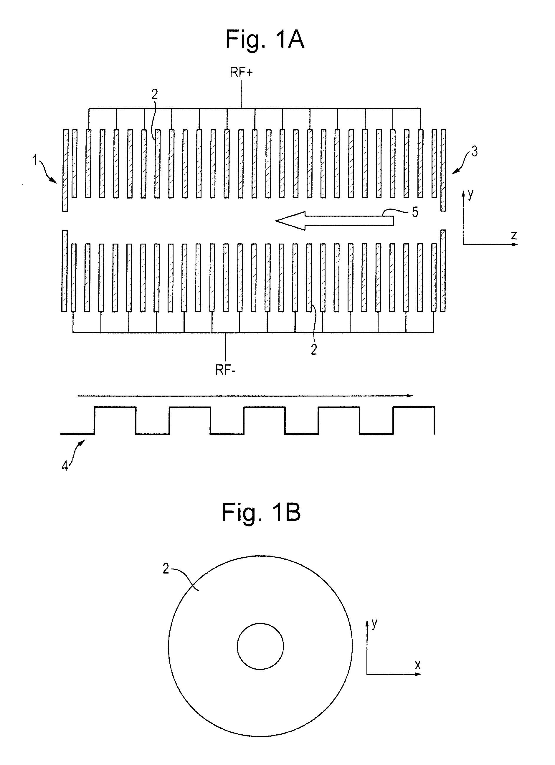
[0248]A preferred embodiment of the present invention will now be described with reference to FIG. 1A.

[0249]FIG. 1A shows a preferred embodiment of the invention wherein an ion mobility separator or other separation device is provided comprising an RF confined ring stack arrangement. The RF ring stack preferably comprises an entrance electrode 1, a series of intermediate ring electrodes 2 and an exit electrode 3. Opposite phases of an AC potential oscillating at RF frequency are preferably applied to alternate ring electrodes 2 in order to produce a radial RF confining force or pseudo-potential. The ring stack preferably comprises a plurality of electrodes each having an aperture through which ions are transmitted in use. Alternative embodiments are also contemplated wherein the ion mobility separator or other separation device comprises a segmented multipole rod set or a plurality of planar electrodes arranged generally in a plane parallel to the plane in which ions travel through ...


PUM

PropertyMeasurementUnit
velocityaaaaaaaaaa
Pressuresaaaaaaaaaa
Pressuresaaaaaaaaaa

Abstract

A method of separating ions according to mass to charge ratio is disclosed. The method comprises: providing a separation device comprising a plurality of electrodes; applying one or more transient DC voltages or potentials to at least some of said electrodes in order to urge ions in a first direction through said separation device; and providing a gas flow in a second direction which is substantially inclined or opposed to said first direction. The opposed gas flow unexpectedly improves the mass to charge ratio separation resolution of the device.

Description

CROSS-REFERENCE TO RELATED APPLICATION[0001]This application claims priority from and the benefit of United Kingdom patent application No. 1323004.0 filed on 24 Dec. 2013 and European patent application No. 13199573.0 filed on 24 Dec. 2013. The entire contents of these applications are incorporated herein by reference.BACKGROUND TO THE PRESENT INVENTION[0002]The present invention relates to an ion separation device.[0003]Ion mobility spectrometers or separators are well known. One particular known ion mobility separator is described with reference to FIG. 7 of US-6630662 (Loboda). The known ion mobility separator comprises a segmented quadrupole rod set ion mobility separator. An axial DC voltage gradient is maintained along the length of the ion mobility separator and a counterflow of gas is provided.[0004]One problem with the known arrangement is that the ion mobility separator is essentially equivalent to a conventional ion mobility separator having a longer drift length.[0005]Al...

Claims


Application Information

Patent Timeline
Patent Type & Authority Applications(United States)
IPC IPC(8): G01N27/62H01J49/42H01J49/40
CPCG01N27/622H01J49/421H01J49/40
Inventor GILES, KEVINGREEN, MARTIN RAYMONDLANGRIDGE, DAVID J.PRINGLE, STEVEN DEREKWILDGOOSE, JASON LEE
Owner MICROMASS UK LTD
Why Eureka
Try Eureka