Unlock instant, AI-driven research and patent intelligence for your innovation.

Node device

a node and device technology, applied in the field of node devices, can solve the problems of long time, large time, and inability to always arrive at the destination of data, and achieve the effect of reducing the time required to arriv

Active Publication Date: 2016-11-03
NEC CORP
View PDF12 Cites 2 Cited by
  • Summary
  • Abstract
  • Description
  • Claims
  • Application Information

AI Technical Summary

Benefits of technology

The present invention solves the problem for users who have difficulty selecting a destination node for DTN communication using delivery predictability. The invention allows users to easily select destination nodes through the use of the delivery predictability.

Problems solved by technology

As mentioned before, a DTN enables end-to-end delivery of transfer data with high reliability even in a condition that connectivity between nodes is unstable and low-quality.
However, transfer data does not always arrive at a destination node from a source node quickly, and it sometimes takes a long time to arrive.
Then, it varies depending on destination nodes whether transfer data quickly arrives or it takes a considerable time to arrive.
However, the transfer data delivery predictability for a destination node of each node is merely used for route control and even existence thereof is not recognized by the users.
Therefore, it is difficult for the user of a source node to select a destination node by using the delivery predictability.

Method used


Image

  • Node device
  • Node device
  • Node device

Examples


first exemplary embodiment

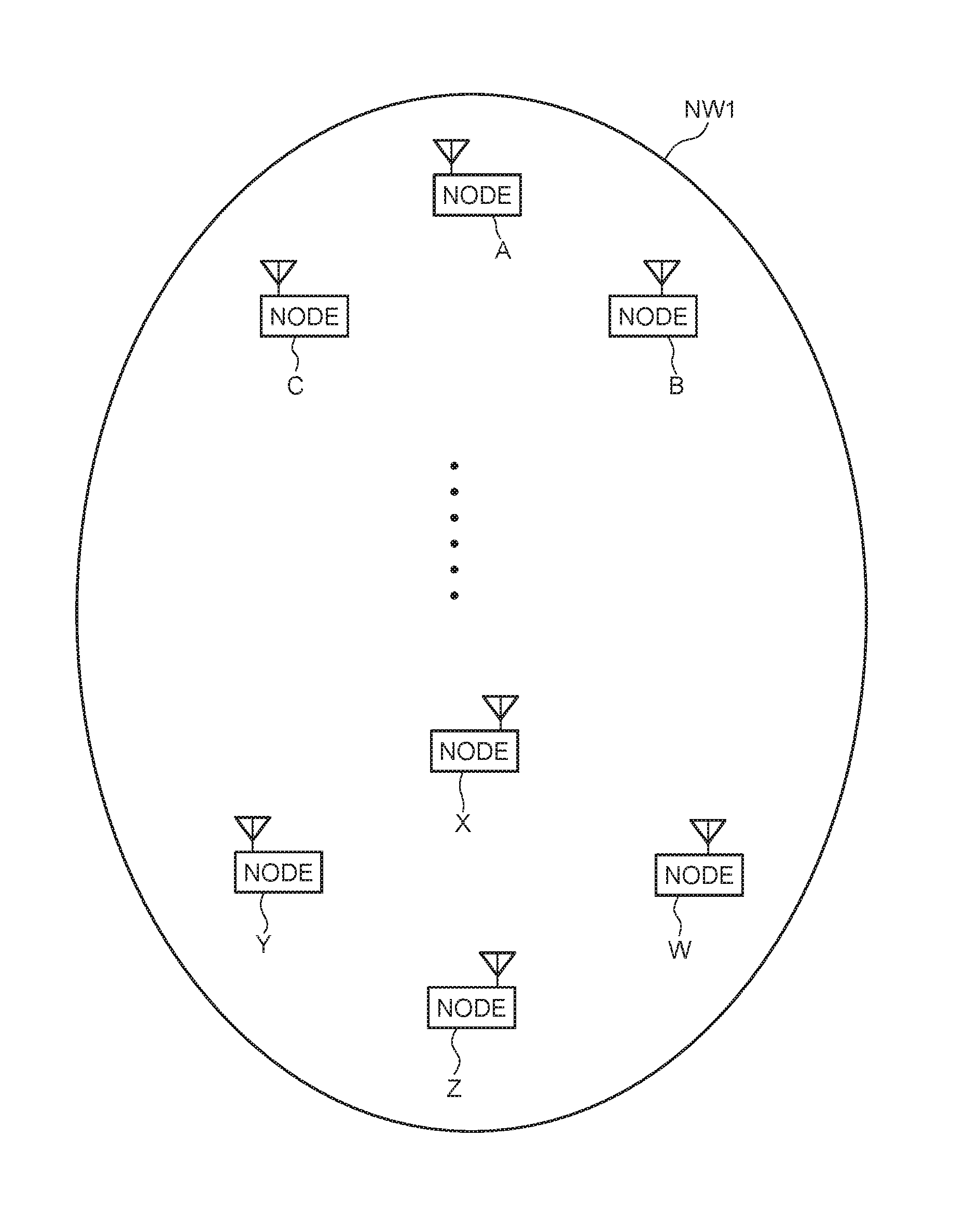
[0056]Referring to FIG. 1, a communication network system NW1 according to a first exemplary embodiment of the present invention is a delay tolerant network which temporarily stores transfer data in a midpoint node and thereby enables delivery without end-to-end reachability from a source node to a destination node. The communication network system NW1 is configured by a node A, a node B, a node C,. . . , a node W, a node X, a node Y, and a node Z. The number and arrangement of the nodes may be any number and arrangement, and the respective nodes A to Z can move.

[0057]FIG. 2 shows the configuration of a node 100 which can be used as each of the nodes A to Z. The node 100 has a wireless communication part 101, an operation input part 102, a screen display part 103, a storage part 104, an arithmetic processing part 105, and an antenna 106.

[0058]The wireless communication part 101 has a function of exchanging communication messages with another node by radio, such as NFC (Near Field Co...

second exemplary embodiment

[0102]Referring to FIG. 15, a communication network system NW2 according to a second exemplary embodiment of the present invention is a network which has a wireless ad hoc network function and a mobile phone network function in addition to the DTN function. The communication network system NW2 is configured by a node A, a node B, a node C, . . . , a node W, a node Y and a node Z. In the example shown by FIG. 15, because direct routes are present between the nodes A, B and C, a small-scale ad hoc network is formed by the three nodes. Moreover, because direct routes are present between the nodes X, Y, Z and W, another small-scale ad hoc network is formed by the four nodes. The number and arrangement of the nodes may be any number and arrangement, and the nodes A to Z can move.

[0103]FIG. 16 shows the configuration of a node 200 which can be used as each of the nodes A to Z. The node 200 has wireless communication parts 201 and 207, an operation input part 202, a screen display part 203...


PUM


Abstract

A node device has a delivery predictability management part, a DTN communication part, and a user interface part. The delivery predictability management part stores, for each destination node, delivery predictabilities including a delivery predictability for the destination node calculated by a local node and a delivery predictability for the destination node calculated by a neighboring node. The DTN communication part refers to the delivery predictabilities for each destination node and selects a next hop node in transferring transfer data from the local node to the destination node. The user interface part allows selection of a destination node for DTN communication with the local node as a source node on a basis of the delivery predictabilities for each destination node.

Description

TECHNICAL FIELD[0001]The present invention relates to a node device, a communication network system, a destination node selection method and a program that are used in a delay tolerant network.BACKGROUND ART[0002]A Delay Tolerant Network (DTN) having a function of temporarily storing transfer data without immediately transferring to a next hop is a network system which enables end-to-end delivery of transfer data with high reliability even in a condition that connectivity between nodes is unstable and low-quality, such as a wireless ad hoc network and a satellite network.[0003]In a DTN, transfer data is divided into unit sizes called bundles and a process of transferring to a destination is executed on each bundle. The greatest characteristic of a DTN is, when a route to the destination of a bundle to transfer is unknown, storing the bundle and waiting until a next hop to transfer the bundle is found without discarding the bundle. By performing such an operation, even when an end-to...

Claims


Application Information

Patent Timeline
Patent Type & Authority Applications(United States)
IPC IPC(8): H04W40/34H04B1/713H04L12/26H04M1/725H04M1/724
CPCH04W40/34H04M1/72519H04W84/18H04L43/16H04B1/713H04W40/00H04W40/18H04M2250/64H04M1/724
Inventor FUJITA, NORIHITOYAMAGAKI, NORIOUEDA, HIROFUMIKINOSHITA, SHUNICHI
Owner NEC CORP