Hydraulic tensioning device for a traction mechanism drive

a technology of hydraulic tensioning device and traction mechanism, which is applied in the direction of gearing, belt/chain/gearing, mechanical apparatus, etc., can solve the problems of inaccurate and cost-intensive finishing of individual parts, and achieve the effect of inexpensive design and simple installation

Active Publication Date: 2016-11-10
SCHAEFFLER TECH AG & CO KG
View PDF4 Cites 15 Cited by
  • Summary
  • Abstract
  • Description
  • Claims
  • Application Information

AI Technical Summary

Benefits of technology

[0005]It is an object of the present invention to provide a hydraulic tensioning device, in which a pressure relief valve simple to install in the piston and having an inexpensive design, is used as an independent assembly.
[0006]According to the present invention a hydraulic tensioning device is provided, in which a premountable valve group is inserted into a central receptacle of the piston as a pressure relief valve on the pressure chamber side in a force- and / or form-fitting manner. The valve group forming an independent assembly of the piston includes a pot-shaped valve housing, also referred to as a valve cap, into which a guide element including the respective valve seat, a valve body and a compression spring are integrated. It is thus possible to implement a valve group of a simple design, optimized with regard to cost and components as a pressure relief valve, which is still mountable in the piston on the pressure chamber side in a simplified manner without a positional orientation.
[0007]The present invention advantageously offers the possibility of implementing a pressure relief valve, which forms an independent assembly, including a minimum of individual components due to the design of the premountable valve group. At the same time, there may be a fluid-tight and air-tight joining of the valve group in the piston without prior complex machining of the joined components. A further cost reduction is achieved through the concept according to the present invention due to the fact that it is sufficient to replace the valve group if leakage of the pressure relief valve occurs as part of a leakage test. Both the piston and the valve seat are usually manufactured as hardened components. With previous approaches, a very accurate and cost-intensive finishing of these individual parts was necessary to permit a press fit. Due to the concept according to the present invention, these components may be joined inexpensively without reworking and consequently may be manufactured with a greater tolerance.
[0009]The valve housing may be pressed into the receptacle in the form of a central bore in the piston as a measure to achieve a quick and simplified assembly. To achieve a secure installation position, a coverage ratio between an inside diameter of the piston receptacle and an outside diameter of the valve housing is preferably between 0.5% and 17%.

Problems solved by technology

With previous approaches, a very accurate and cost-intensive finishing of these individual parts was necessary to permit a press fit.

Method used


Image

  • Hydraulic tensioning device for a traction mechanism drive
  • Hydraulic tensioning device for a traction mechanism drive
  • Hydraulic tensioning device for a traction mechanism drive

Examples


Embodiment Construction

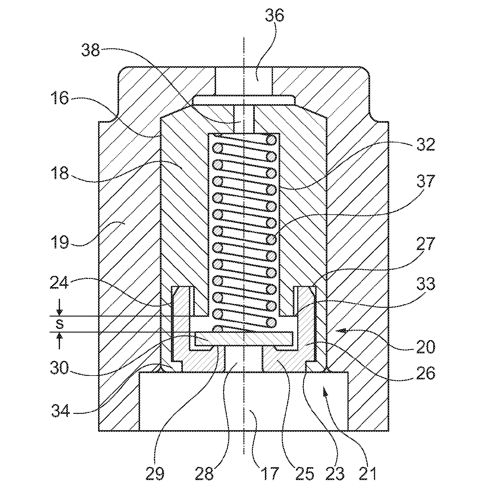
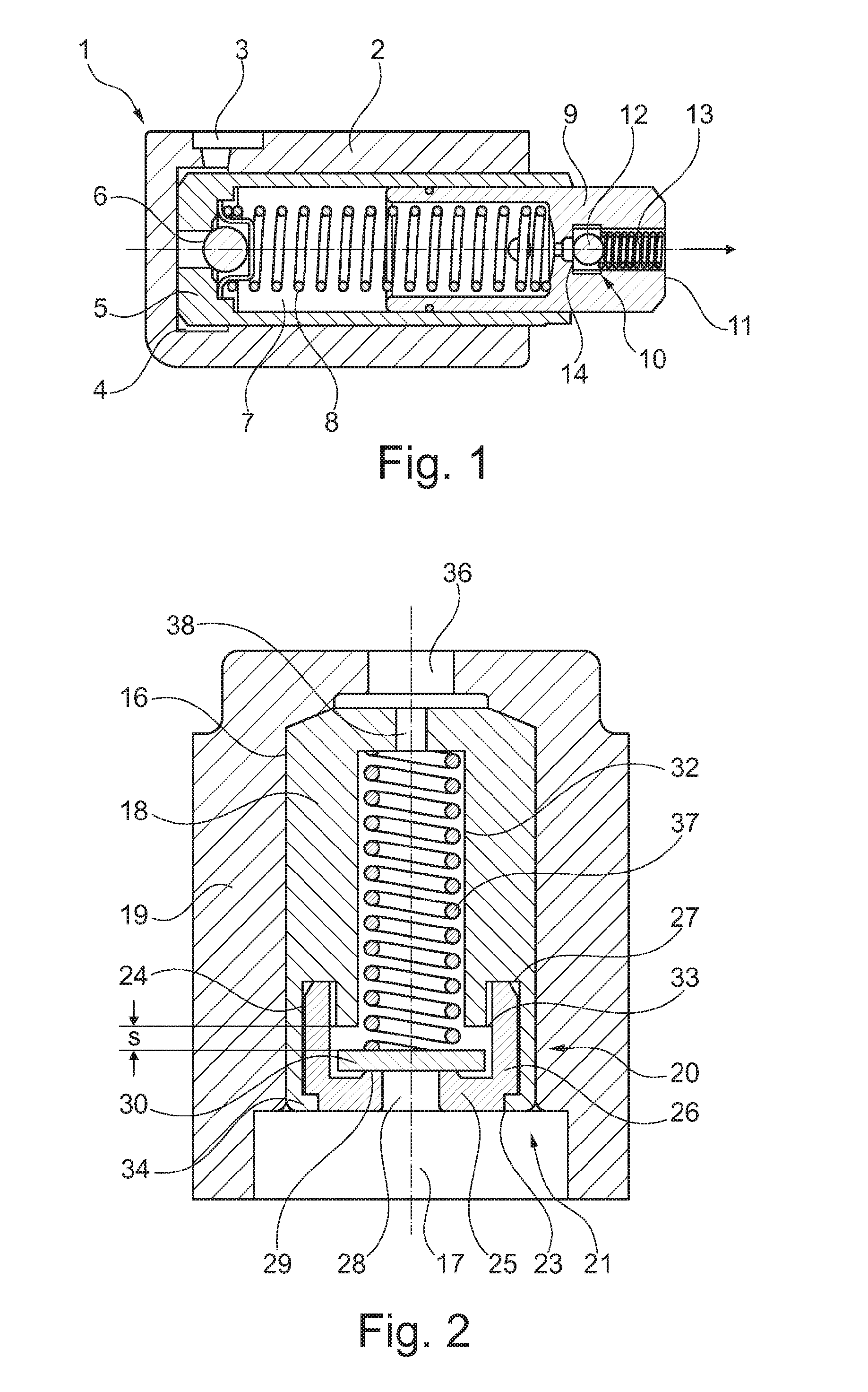
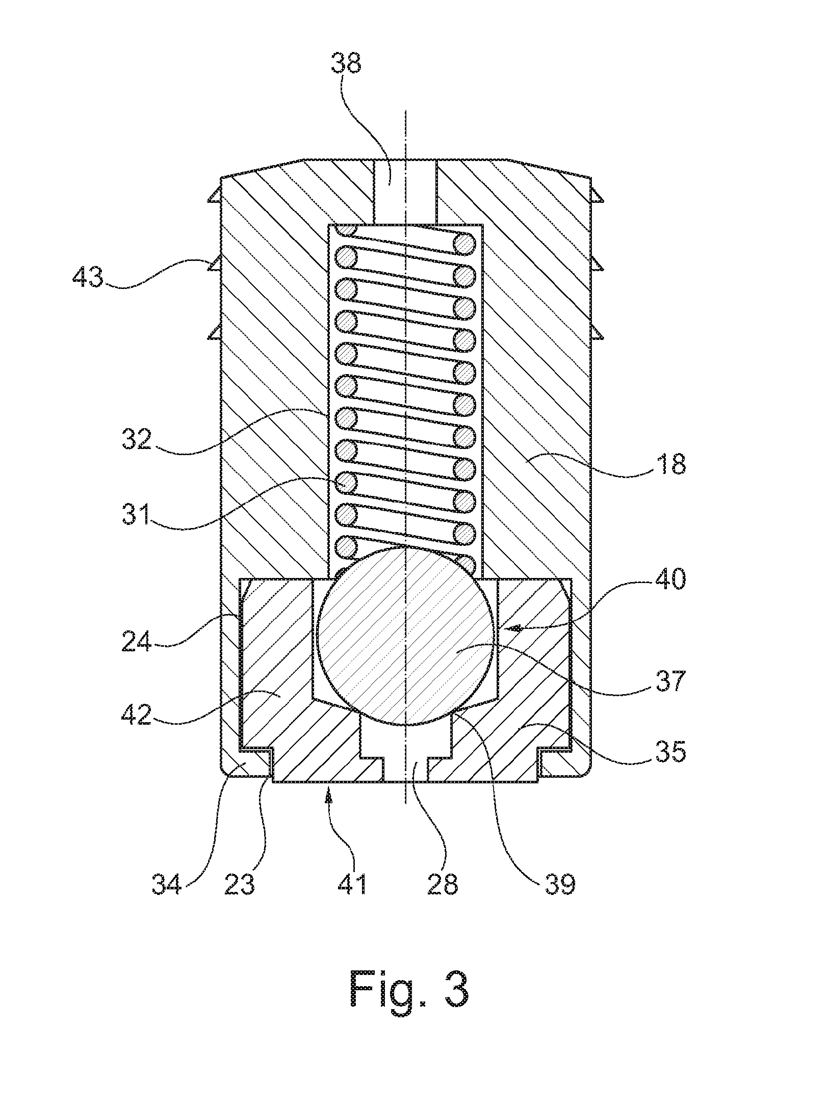
[0019]FIG. 1 shows a hydraulic tensioning device 1 including a housing 2, which includes a pressure oil connection 3, starting from which oil as hydraulic fluid enters an annular space 4. The oil flows through a non-return valve 6, inserted into a cylinder 5 at the bottom, into a pressure chamber 7 and acts upon it, supported by a compression spring 8 introduced into the pressure chamber 7, a piston 9 in the direction of the arrow, operatively connected in the installed condition directly or indirectly to a traction means, for example, a chain of a traction mechanism drive (not shown). On the side facing away from the pressure chamber 7 in a piston bottom 11, a pressure relief valve 10 is integrated into piston 9. Pressure relief valve 10, which opens toward the outside, is inserted centrally into piston 9 and includes a valve body 12, which is designed as a ball and is sealingly supported on a valve seat 14 in the closed condition with the aid of a compression spring 13.

[0020]FIG. ...


PUM


Abstract

The invention relates to a hydraulic tensioning device, which is used in traction drives of internal combustion engines and which comprises a piston (19) that is supplied with a hydraulic fluid. The piston is movably guided in a linear manner in a cylinder and is spring-loaded against a traction means. The hydraulic fluid can flow into a pressure chamber (17) via a non-return valve or out of the pressure chamber (17) via a pressure-relief valve (20), depending on an adjustment movement direction of the piston (19). For this purpose, the pressure-relief valve (20) is inserted in a central receiving area (16) of the piston (19) on the pressure-chamber side as a valve group (21) which can be mounted upstream and comprises a pot-shaped valve housing (18) and into which a guide element (25) with a corresponding valve seat (29), a valve element designed as a valve plate (30), and a pressure spring (31) are integrated.

Description

[0001]The present invention relates to a hydraulic tensioning device which is used in traction mechanism drives of internal combustion.BACKGROUND[0002]Hydraulic tensioning devices are used primarily for traction mechanism drives such as chain or belt drives which effectively compensate for a changing length of the traction means in the operating condition due to heating and / or wear. To reduce force peaks in a traction mechanism drive and thus in the hydraulic tensioning device, it is known that a pressure relief valve may be assigned to the pressure chamber of the tensioning device.[0003]A tensioning device of the design described above is known from DE 36 39 389 A1 in which a chain as the traction means is tensioned. The design of the tensioning device includes an inflow opening in the housing of the tensioning device designed as a cylinder in which a spring-loaded non-return valve is situated. A spring-loaded pressure relief valve is inserted into the outflow channel introduced in...

Claims


Application Information

Patent Timeline
Patent Type & Authority Applications(United States)
IPC IPC(8): F16H7/08
CPCF16H7/0836F16H2007/0859F16H2007/0814F16H2007/0806
Inventor FISCHER, MARKUSNESS, FRIEDRICH
Owner SCHAEFFLER TECH AG & CO KG
Why Eureka
Try Eureka