Suspended Track and Planar Electrode Systems and Methods

a planar electrode and track technology, applied in the direction of semiconductor devices for light sources, lighting and heating apparatus, lighting support devices, etc., can solve the problems of difficult installation of systems, requiring turnbuckles and other relatively expensive elements and tools, positioning and routing of electrodes through space or along a surface in anything but a straight path can be difficult, and special elements are required to change electrode direction

Active Publication Date: 2016-11-10
APEX TECH INC
View PDF27 Cites 9 Cited by
  • Summary
  • Abstract
  • Description
  • Claims
  • Application Information

AI Technical Summary

Benefits of technology

[0012]For purposes of this disclosure, a “twist-on” element is an element that uses rotation about any axis in order to make a mechanical engagement with at least one electrode. The mechanical engagement may include an interference fit which restricts relative movement or a loose coupling that allows relative movement in at least one direction after coupling. It has been found that loose coupling to electrodes with twist-on elements can be particularly advantageous when the parallel electrodes are not maintained as linear segments before or after attachment. Loose and / or tight coupling may be incorporated in the various embodiments by reducing clearance dimensions between slot features and electrode outer diameters or incorporating protrusions or channels that cause electrodes to deviate from straight paths through the element after twisting.

Problems solved by technology

Some systems are difficult to install and require turnbuckles and other relatively expensive elements and tools to make mechanical and electrical attachments.
Positioning and routing of the electrodes through a space or along a surface in anything but a straight path can be difficult or require special elements to change electrode direction.
Spacers to maintain uniform spacing between cable or rod electrodes that require installation from only ends of the electrodes are inconvenient to assemble onto long lengths of electrode.
Interference-fit spacers that snap onto cylindrical electrodes through relative movement along one direction are often difficult to install.
The relatively small electrode diameters may also make mechanical tolerances requirements difficult to achieve for a reliable interference fit of an electrode forced into a conventional snap-fit slot feature.
The forces required to overcome the snap constriction may lead to permanent deformation of the electrodes especially in installation environments that have limited clearance for snapping the electrodes into a spacer.
While flexible track systems are known that can bend to some extent in a direction perpendicular to the track substrate, changing direction in the plane of the electrodes (that is, along the mounting surface) may require special turning elements that restrict three-dimensional paths, make installation difficult and / or increase costs.
This pointing flexibility generally increases system size, weight, and the number of parts of the fixture which usually increases system costs and may negatively impact industrial design options.
While these cable and track lighting systems provide more flexibility than stationary lighting fixtures, they do not meet all of the needs for easily initially configuring and subsequently changing lighting in a space.

Method used


Image

  • Suspended Track and Planar Electrode Systems and Methods
  • Suspended Track and Planar Electrode Systems and Methods
  • Suspended Track and Planar Electrode Systems and Methods

Examples


Embodiment Construction

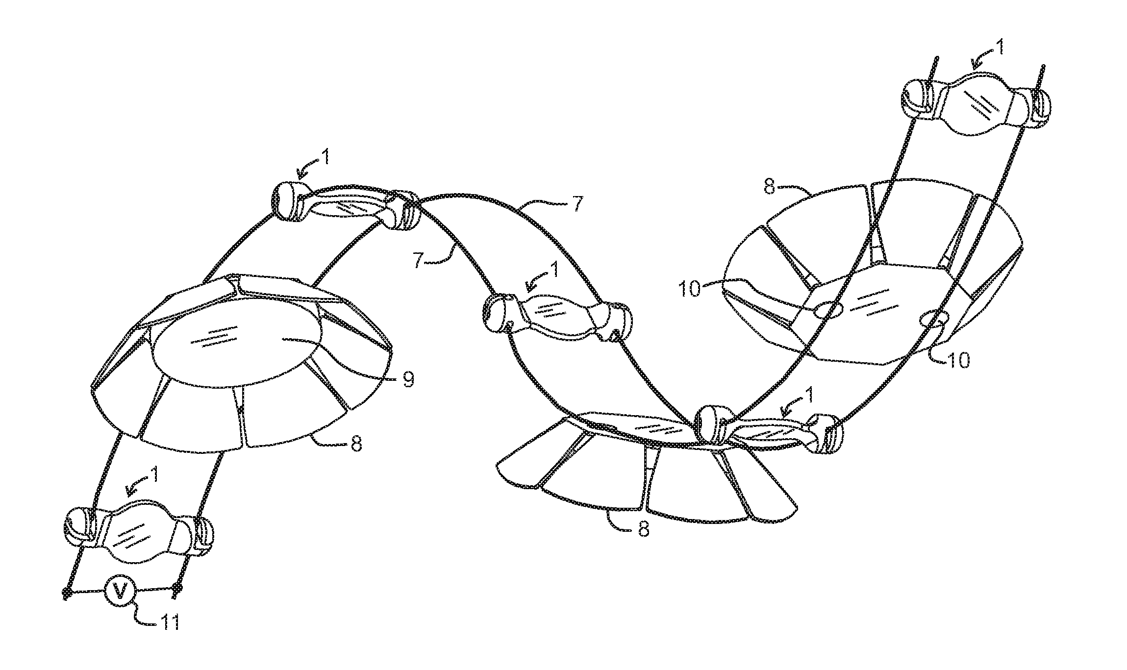
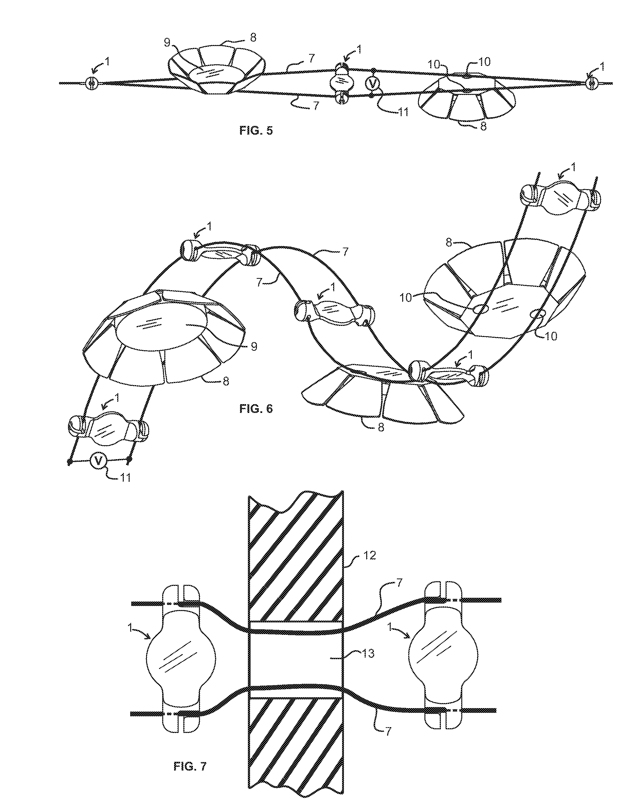
[0108]Referring to FIG. 1 through FIG. 4 illustrating a first embodiment, the electrode track system is comprised of a twist-lock electrode spacer 1 and two electrode rails 7. The twist-lock electrode spacer 1 is comprised of an electrically insulating body 2 (or a body coated with an insulating layer) and may be made from materials such as injection-molded engineering thermoplastics (polycarbonate, ABS, polystyrene, etc.). Spacer 1 contains radial wire insertion slots 3 on each end of spacer 1, and circumferential arc electrode locking slots 4 that intersect with insertion slots 3. Electrode locking slots 4 in this embodiment are configured to extend approximately 90 degrees around the axis of the spacer. As an example, spacer 1 may be configured with circumferential locking slots 4 located approximately 1.5 inches apart (distance CS' in FIG. 1), and the width of the slots approximately 0.08″ wide to accommodate a 0.08″ diameter electrode material, with a general outside diameter o...


PUM


Abstract

Suspended and planar electrode systems and methods are disclosed for applications such as lighting. Some embodiments incorporate removable twist-on elements providing uniform spacing between cable rod or strip electrodes extending through space. Multiple electrodes may be attached simultaneously. Twist-on elements may contain light emitting elements electrically attached to parallel electrodes. Embodiments may include mounting features for fixing electrodes above a mounting surface. Some embodiments include electrically insulated electrodes and modules with insulation displacement contact elements and environmental sealing. Some embodiments include polymeric insulation on both the module and electrodes providing environmental sealing when modules are disconnected from electrodes. Electrodes in sealed systems may be suspended with spacers or built into planar arrays in walls, ceiling or furniture. Some embodiments include folded electrode gyrating tracks having mounting positions providing different axial and radial pointing directions. Modules may be attached to electrodes by mechanical or magnetic forces.

Description

BACKGROUND OF THE INVENTION[0001]Cable lighting systems are known in which lighting fixtures are attached between flexible parallel electrodes that are maintained straight through tension. Some systems are difficult to install and require turnbuckles and other relatively expensive elements and tools to make mechanical and electrical attachments. Positioning and routing of the electrodes through a space or along a surface in anything but a straight path can be difficult or require special elements to change electrode direction.[0002]Spacers to maintain uniform spacing between cable or rod electrodes that require installation from only ends of the electrodes are inconvenient to assemble onto long lengths of electrode. Pre-attached spacers may prevent insertion of the electrodes through an opening that is smaller than the electrode spacing.[0003]Interference-fit spacers that snap onto cylindrical electrodes through relative movement along one direction are often difficult to install. T...

Claims


Application Information

Patent Timeline
Patent Type & Authority Applications(United States)
IPC IPC(8): F21S2/00F21V21/35F21V21/096F21V23/06F21V31/00
CPCF21S2/005F21V23/06F21V21/35F21V21/096F21V31/005F21V21/008F21Y2115/10
Inventor RUDISILL, CHARLES ALBERTWHITTLE, DANIEL JOHN
Owner APEX TECH INC
Why Eureka
Try Eureka