Antenna device and portable wireless terminal equipped with the same

a portable wireless terminal and antenna technology, applied in the field of array antennas, can solve problems such as degradation of antenna performan

Active Publication Date: 2015-08-11
PANASONIC INTELLECTUAL PROPERTY MANAGEMENT CO LTD
View PDF17 Cites 4 Cited by
  • Summary
  • Abstract
  • Description
  • Claims
  • Application Information

AI Technical Summary

Benefits of technology

[0020]According to the antenna device of the present invention and portable wireless terminal equipped with the same, in a case where the antenna elements are disposed to be close, it is possible to achieve a loosely coupled array antenna device and a portable wireless terminal equipped with the same without connecting the antenna elements through components and the like.

Problems solved by technology

Thus, there is a serious problem in that degradation in the antenna performance is caused by coupling between the plurality of antenna elements.
Further, a high-performance antenna system, which is subject to the coupling degradation countermeasures by reducing the number of power supply paths and the number of antenna elements as much as possible, is required.

Method used


Image

  • Antenna device and portable wireless terminal equipped with the same
  • Antenna device and portable wireless terminal equipped with the same
  • Antenna device and portable wireless terminal equipped with the same

Examples


embodiment 1

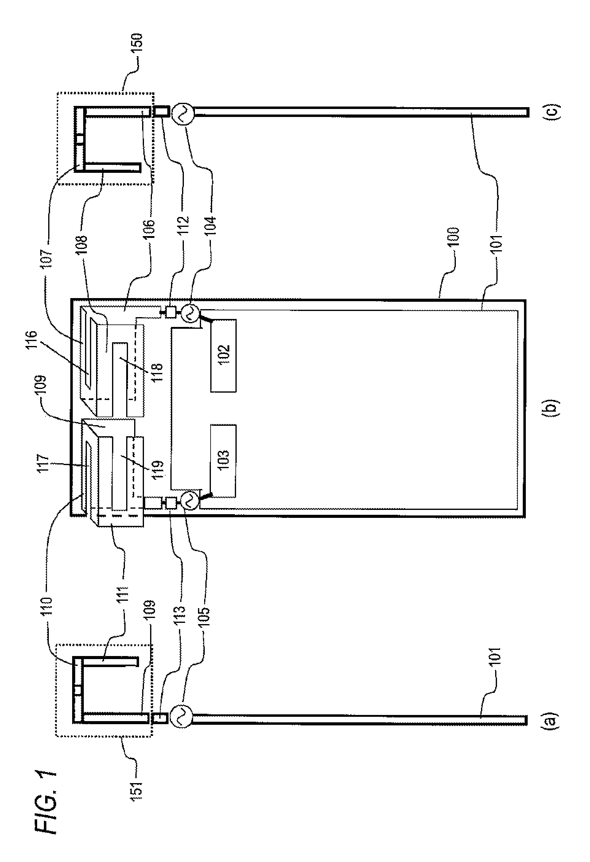
[0028]FIGS. 1(a) to 1(c) are configuration diagrams of a portable wireless terminal according to Embodiment 1 of the present invention. FIG. 1(a) is a configuration diagram of the portable terminal viewed from the left side, and FIG. 1(b) is a diagram showing a view from the front. Further, FIG. 1(c) is a configuration diagram showing a view from the right side.

[0029]As shown in FIGS. 1(a) to 1(c), a circuit board 101 disposed in the portable wireless terminal 100 includes a first wireless circuit section 102. Thus, a first antenna element150 made of a conductive metal is supplied with a high-frequency signal through a first power supply section 104.

[0030]Here, the first antenna element 150 includes: a first conductor plate 106 which is conductive and substantially rectangular; a second conductor plate 107 which shares one side of the first conductor plate 106 in a widthwise direction thereof, is disposed thereon at approximately 90 degrees, and is substantially rectangular; and a t...

embodiment 2

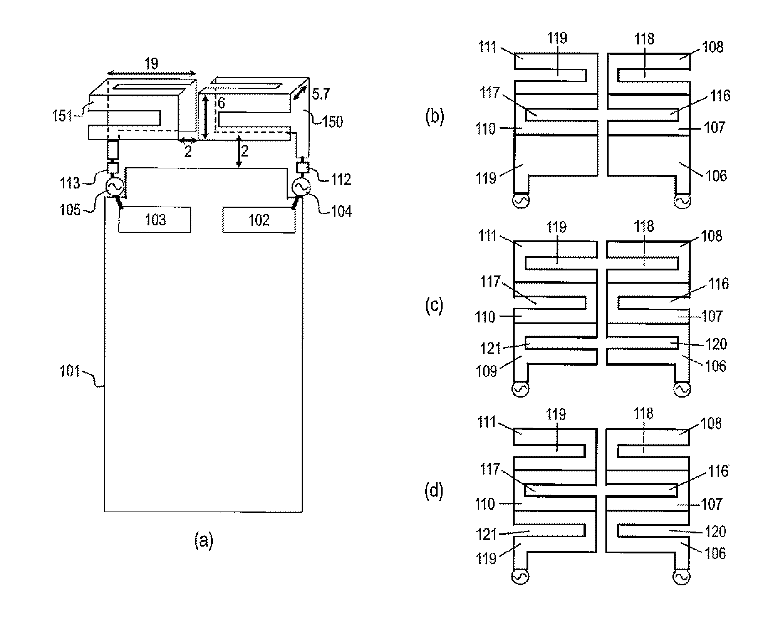
[0069]FIGS. 5(a) to 5(d) are configuration diagrams of a portable wireless terminal according to Embodiment 2 of the present invention. FIG. 5(a) is a diagram showing a view from the front.

[0070]In FIGS. 5(a) to 5(d), the components common to FIGS. 1(a) to 1(c) will be referenced by the same reference numerals and signs, and description thereof will be omitted.

[0071]FIGS. 5(b), 5(c), and 5(d) show variations in the arrangement positions of the slots, which are disposed in the first antenna element 150 and the second antenna element 151, for making the coupling loose.

[0072]As shown in FIG. 5(a), the circuit board 101 is formed as a printed-circuit board made of glass epoxy. However, the circuit board is formed of a copper foil with a length of 85 mm and a width of 42 mm.

[0073]In the circuit board 101, the first antenna element 150 and the second antenna element 151 formed of conductive copper plates are supplied with the high-frequency signal through the first power supply section 10...


PUM


Abstract

A second slit 117 and a fourth slit 119 provided in a first antenna element 150 and a first slit 116 and a third slit 118 provided in a second antenna element 151 are adjusted such that the mutual coupling between the first antenna element 150 and the second antenna element 151 in the desired frequency band is canceled, and reduces degradation in coupling between antenna elements without connecting the antenna elements through components and the like. With such a configuration, it is possible to achieve high-efficiency loosely coupled MIMO array antennas operating in the same frequency band in a portable wireless terminal.

Description

TECHNICAL FIELD[0001]The present invention relates to an antenna device and a portable wireless terminal equipped with the same. In particular, the present invention relates to an array antenna for a portable terminal, and which achieves high antenna efficiency as a result of loose coupling between two adjacent elements.BACKGROUND ART[0002]Portable wireless terminals such as mobile phones have been developed to have more and more functions, for example not only the telephone function, the electronic mail function, and the function of access to the Internet, but also the near-field wireless communication function, the wireless LAN function, the GPS function, the TV-viewing function, the IC card transaction function, and the like. In addition, in cellular communication, as a technique for achieving a high-speed and high-capacity wireless communication system, it can be expected to provide spatial multiplexing transfer (MIMO: Multi-Input Multi-Output) for performing communication by us...

Claims


Application Information

Patent Timeline
Patent Type & Authority Patents(United States)
IPC IPC(8): H01Q21/00H01Q21/28H01Q9/42H01Q1/36H01Q1/52H01Q1/24
CPCH01Q1/36H01Q1/52H01Q9/42H01Q21/28H01Q1/243
Inventor SATOU, HIROSHIHIROBE, TAKANORIKOYANAGI, YOSHIONISHIKIDO, TOMOAKI
Owner PANASONIC INTELLECTUAL PROPERTY MANAGEMENT CO LTD
Why Eureka
Try Eureka