Refrigeration apparatus

Active Publication Date: 2016-11-10
ASAHI GLASS CO LTD +1
View PDF15 Cites 5 Cited by
  • Summary
  • Abstract
  • Description
  • Claims
  • Application Information

AI Technical Summary

Benefits of technology

The present invention relates to a refrigeration apparatus that uses HFO1123 or a refrigerant mixture containing HFO1123 as the refrigerant. This results in reduced global warming and less energy applied to the refrigerant, which improves safety and reduces the occurrence of disproportional reactions. Additionally, the apparatus reduces the shock pressure due to water hammer action at the expansion valve. This leads to improved efficiency and reduced energy waste.

Problems solved by technology

However, since this refrigerant has a high boiling point and low performance, there are many technical problems in efforts to maintain performance equal to that of the conventional refrigerant, leading to an increased cost.

Method used


Image

  • Refrigeration apparatus
  • Refrigeration apparatus
  • Refrigeration apparatus

Examples


embodiment 1

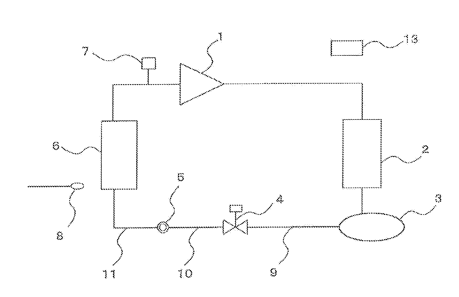
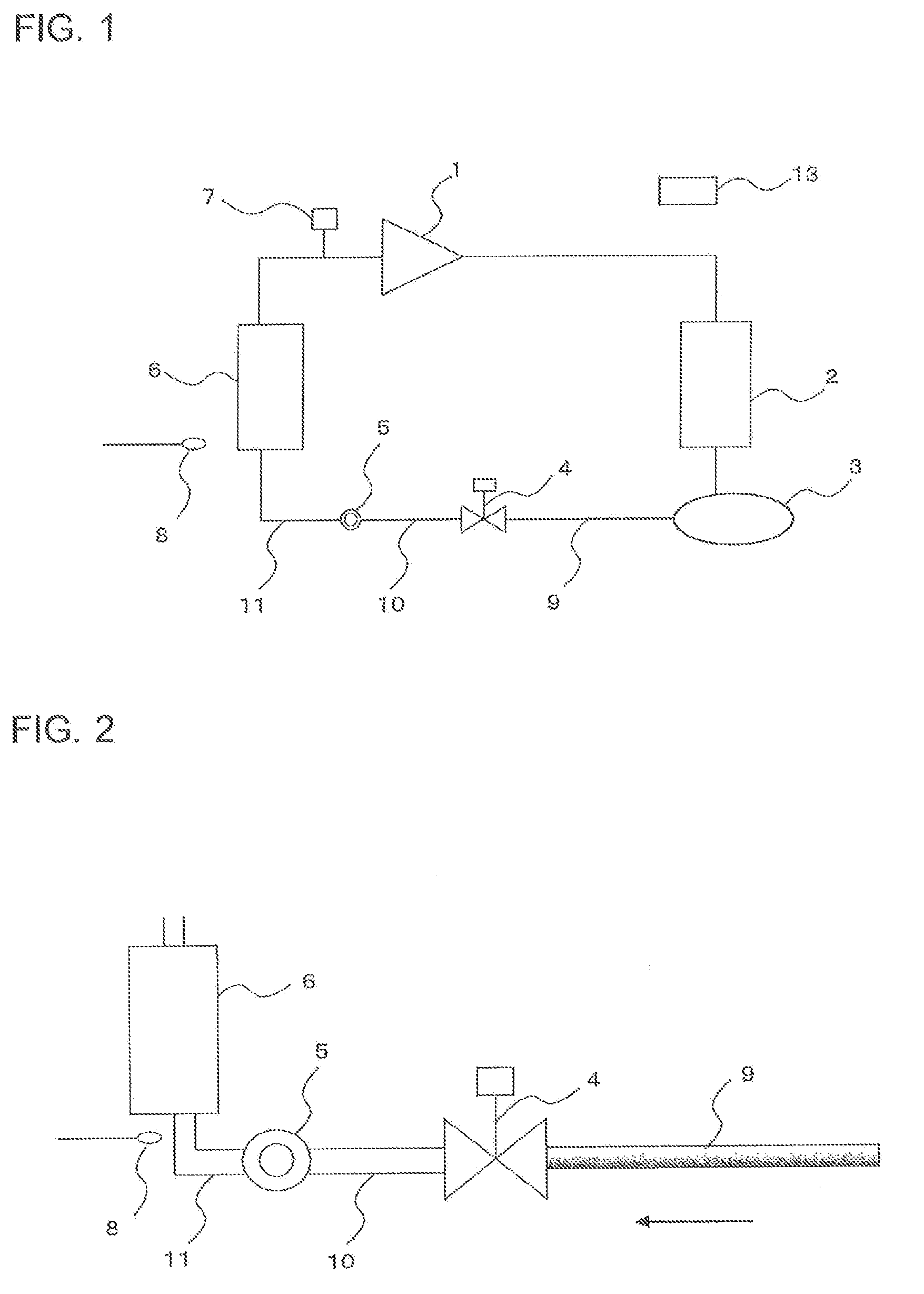
[0023]FIG. 1 is a refrigerant circuit diagram of a refrigeration apparatus according to Embodiment 1 of the present invention, and FIG. 2 shows an enlargement of the principal part of the refrigerant circuit diagram of the refrigeration apparatus according to Embodiment 1 of the present invention. Arrow in FIG. 2 shows the flowing direction of refrigerant, and this also applies to FIGS. 3 to 5 described later.

[0024]The refrigeration apparatus according to Embodiment 1 is used, for example, as a refrigerator, a freezer, a showcase, and a unit cooler, and includes a refrigerant circuit in which a compressor 1, a condenser 2, a liquid receiver 3, a solenoid valve 4, an expansion valve 5, and an evaporator 6 are connected in order by pipes. The refrigeration apparatus further includes a controller 13. A pressure sensor 7 is provided on a suction side (low-pressure side) of the compressor 1, and a temperature sensor 8 is provided in a cooling target space near the evaporator 6 (for examp...

embodiment 2

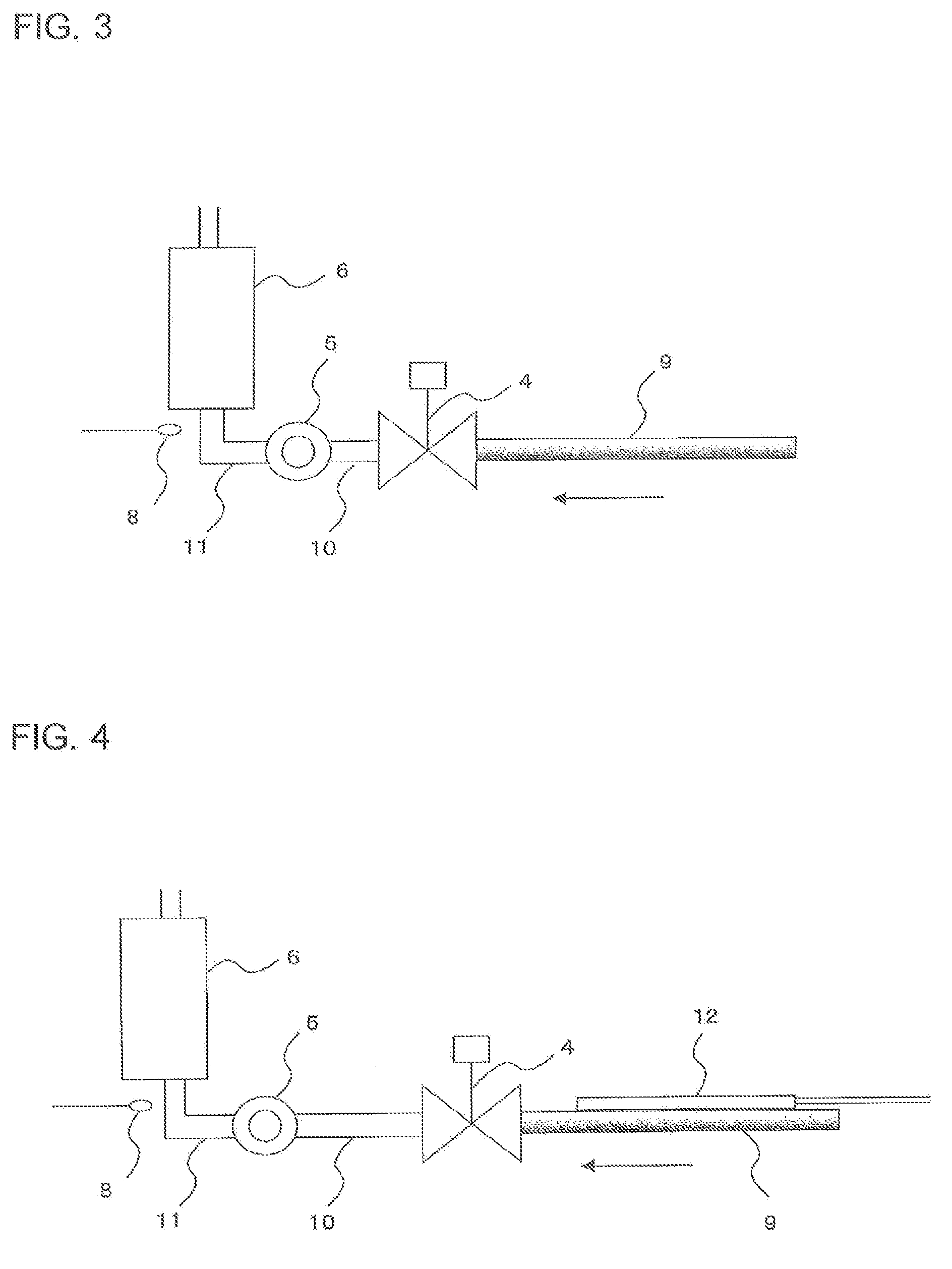
[0043]FIG. 3 shows an enlargement of the principal part of a refrigerant circuit diagram of a refrigeration apparatus according to Embodiment 2 of the present invention.

[0044]While Embodiment 2 will be described below, descriptions of components same as those of Embodiment 1 are omitted, and components identical or corresponding to those of Embodiment 1 are denoted by the same reference numerals.

[0045]In Embodiment 2, the length of a second pipe 10 that connects a solenoid valve 4 and an expansion valve 5 is set to be less (50 mm or less) than conventional ones. When the length of the second pipe 10 is 50 mm or less, the capacity of the second pipe 10 is less than or equal to about 30 cc.

[0046]Since the distance between the solenoid valve 4 and the expansion valve 5 is thereby shortened, the shock pressure due to a water hammer action can be reduced, and the energy applied to refrigerant can be reduced to less than a fixed amount. For this reason, the occurrence of a disproportional...

embodiment 3

[0047]FIG. 4 shows an enlargement of the principal part of a refrigerant circuit diagram of a refrigeration apparatus according to Embodiment 3 of the present invention.

[0048]While Embodiment 3 will be described below, components overlapping with those of Embodiment 1 are omitted, and components identical or corresponding to those of Embodiment 1 are denoted by the same reference numerals.

[0049]In Embodiment 3, a first pipe 9 that connects a liquid receiver 3 and a solenoid valve 4 is provided with a heater 12. The heater 12 is formed by, for example, a heating wire, and is energized to heat the first pipe 9. The temperature of the heated first pipe 9 rises, and the temperature of liquid refrigerant that fills the first pipe 9 also rises. Since a part of the liquid refrigerant is gasified, the liquid refrigerant is easily compressed. This can reduce the shock pressure due to a water hammer action and can limit energy applied to the refrigerant to less than a fixed amount. For this r...


PUM


Abstract

A refrigeration apparatus includes a refrigerant circuit in which a compressor, a condenser, a liquid receiver, a first opening-and-closing valve, an expansion valve, and an evaporator are connected sequentially by pipes and through which refrigerant circulates. The refrigerant is HFO1123 or a refrigerant mixture containing HFO1123. A ratio of a refrigeration capacity to an opening area of the first opening-and-closing valve is within a range of 0.25 to 0.6 (kw / mm2).

Description

TECHNICAL FIELD[0001]The present invention relates to a refrigeration apparatus that suppresses the influence on global warming.BACKGROUND ART[0002]There has conventionally been a refrigeration apparatus constituted by a refrigerant circuit in which a compressor, a condenser, a liquid receiver, an expansion valve, and an evaporator are connected in order by pipes (see, for example, Patent Literature 1).[0003]In some refrigeration apparatuses of this type, a solenoid valve is provided between the liquid receiver and the expansion valve, a pressure sensor is provided on a suction side of the compressor, and a temperature sensor is provided in a cooling target space near the evaporator. When the temperature in the cooling target space detected by the temperature sensor becomes lower than a predetermined value, the solenoid valve closes and refrigerant is collected in the liquid receiver (pump-down). When the pressure detected by the pressure sensor becomes lower than a predetermined va...

Claims


Application Information

Patent Timeline
IPC IPC(8): F25B49/02F25B41/06
CPCF25B49/02F25B49/022F25B41/062F25B2500/27F25B2500/07F25B2500/06F25B2400/01F25B2600/021F25B2600/2515F25B2600/2501F25B2700/1933F25B2700/2104F25B2400/16F25B1/00F25B2400/04F25B2500/26Y02B30/70F25B41/24
Inventor SUGIMOTO, TAKESHISAIKUSA, TETSUJI
Owner ASAHI GLASS CO LTD
Why Eureka
Try Eureka