
Long range archery scope

a long-range archery and scope technology, applied in the field of long-range archery scopes, can solve the problems of increasing the difficulty of accurately increasing the difficulty of accuracy aiming guns, and increasing the difficulty of accuracy aiming bows and crossbows, etc., to eliminate or diminish the disadvantages and problems.

Active Publication Date: 2016-11-10
HUSKEMAW OPTICS
View PDF3 Cites 22 Cited by
  • Summary
  • Abstract
  • Description
  • Claims
  • Application Information

AI Technical Summary

Benefits of technology

The patent describes a scope with an adjustment dial that can be moved to different positions to compensate for projectile drops at different distances to a target. The dial is labeled with distance indicators to show the ranges of distances that can be compensated for. The scope can also include windage hold-off indicators to compensate for deflection caused by crosswalls. The adjustment dial can be calibrated using various factors such as sight-height data, muzzle velocity data, and ballistics coefficients. The scope can also be used with interchangeable components that have different calibration data, allowing for flexibility in shooting conditions. Additionally, the patent describes a system that uses a distance calculation module to accurately aim at a target under different shooting conditions.

Problems solved by technology

Because accurately aiming guns may become more difficult as the distance to a target increases, scopes are often uses in connection with guns.
But even when using a scope, shooters may find it difficult and / or time consuming to accurately aim at a target.
Similar to guns, accurately aiming bows and crossbows becomes more difficult as the distance to a target increases, resulting in the use of long-range scopes with bows and crossbows.
However, such long-range scopes tend to be difficult and time consuming due to the many factors the shooter must take into account, such as wind speed and projectile drop of the bullet, arrow or bolt.
Scopes currently known in the art allow the shooter to adjust or calibrate the scope for account for such factors if known, but do not allow the user to do so easily and efficiently because known scopes to do not provide pre-set and / or customized calibration data specific to different guns, bows or crossbows or shooting conditions.

Method used


Image

  • Long range archery scope
  • Long range archery scope
  • Long range archery scope

Examples


Embodiment Construction

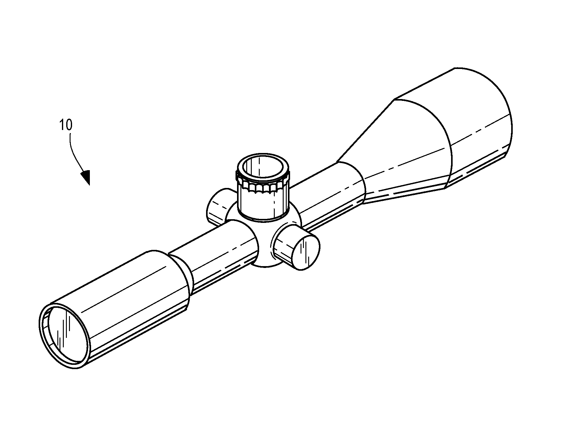
[0041]The invention will now be described with reference to the drawing figures, in which like reference numerals refer to like parts throughout. For purposes of clarity in illustrating the characteristics of the present invention, proportional relationships of the elements have not necessarily been maintained in the drawing figures. It will be appreciated that any dimensions included in the drawing figures are simply provided as examples and dimensions other than those provided therein are also within the scope of the invention.

[0042]The following detailed description of the invention references specific embodiments in which the invention can be practiced. The embodiments are intended to describe aspects of the invention in sufficient detail to enable those skilled in the art to practice the invention. Other embodiments can be utilized and changes can be made without departing from the scope of the present invention. The present invention is defined by the appended claims and the d...


PUM


Abstract

A scope may include an adjustment dial, which may be moved among a plurality of positions to configure the scope to compensate for projectile drops. The adjustment dial may be labeled with dial-calibration data, which may include one or more distance indicators and / or one or more windage hold-off indicators. The scope may be attached to a gun, bow or crossbow and the dial-calibration data may be at least partially generated using ballistics performance data based on shots, bullets, arrows or bolts fired by the gun, bow or crossbow. The dial-calibration data may be at least partially generated using shooting conditions. A system and method for generating customized adjustment dials can incorporate ballistics, projectile, and / or shooting conditions into program. The system and method can also include a derived distance calculation module, which may be configured to use a distance to a target and actual shooting conditions to calculate a derived distance.

Description

CROSS-REFERENCE TO RELATED APPLICATIONS[0001]This Application is a continuation-in-part of and claims priority to U.S. patent application Ser. No. 14 / 623,259, filed on Feb. 16, 2015, entitled “Ballistics Systems and Methods,” currently pending, which is a divisional of and claims priority to U.S. application Ser. No. 14 / 057,810, filed on Oct. 18, 2013, entitled “Ballistics Systems and Methods,” now abandoned, which is a divisional of and claims priority to U.S. application Ser. No. 13 / 745,499, filed on Jan. 18, 2013, entitled “Ballistics Systems and Methods,” now abandoned, which is a divisional of and claims priority to U.S. application Ser. No. 12 / 854,136, filed on Aug. 10, 2010, entitled “Ballistics Systems and Methods,” now U.S. Pat. No. 8,365,455, which is a continuation of and claims priority to U.S. application Ser. No. 11 / 838,183, filed on Aug. 13, 2007, entitled “Ballistics Systems and Methods,” now U.S. Pat. No. 8,001,714, which claims priority to U.S. Provisional Patent A...

Claims


Application Information

Patent Timeline
Patent Type & Authority Applications(United States)
IPC IPC(8): F41G1/38F41G3/08F41G1/467
CPCF41G1/38F41G3/08F41G1/467F41G1/473F41G3/06G01C23/00G05B15/02E05G1/14F41G1/54F41G11/00
Inventor PORTER, JOHN A.PETERSON, JACKDAVIDSON, AARON
Owner HUSKEMAW OPTICS
Learn More