Supercharge Your Innovation With Domain-Expert AI Agents!

Design of a triggering circuit of overvoltage protection with an asymmetric element

a technology of asymmetric elements and triggering circuits, applied in the direction of emergency protective arrangements for limiting excess voltage/current, spark gaps, electrical apparatus, etc., can solve the problems of damage to the triggering circuit, high impedance of the secondary winding, endangering the protected equipment, etc., to facilitate the breakdown and increase the reliability of the triggering

Active Publication Date: 2016-11-10
SALTEK
View PDF8 Cites 5 Cited by
  • Summary
  • Abstract
  • Description
  • Claims
  • Application Information

AI Technical Summary

Benefits of technology

The patent is about a circuit that protects electronic devices from overvoltage events. It uses a spark gap with two main electrodes and an auxiliary electrode to help with the breakdown between them. The circuit has an asymmetric element that triggers the breakdown and makes the circuit more reliable and effective.

Problems solved by technology

The main drawback of known designs of triggering circuits with a transformer is that the size of the current flowing between the auxiliary electrode and main electrode I or main electrode II of the spark gap is considerably limited by the impedance of the transformer secondary winding, which extends the time necessary to trigger the spark gap eventually, the transformer secondary winding can be destroyed by thermal overloading due to the limited cross-section of the transformer secondary winding wires, and consequently, the overvoltage protection device loses its functionality, which then endangers the protected equipment by impulse overvoltage.
The disadvantage of such a design is the secondary winding's high impedance, which limns the current flowing through the auxiliary electrode and one of the main electrodes.
Such overloading can result in damage to the triggering circuit and loss of functionality of the overvoltage protection device.
In this design, the above-stated deficiencies are even greater.
The protective resistor partially protects the winding from damaging, at the same time, however, it limits the current, i.e. the triggering ability of the triggering circuit as well, and, at the same time, the arch stability is limited.
The disadvantage of the secondary windings high impedance of the transformer persists.

Method used


Image

  • Design of a triggering circuit of overvoltage protection with an asymmetric element
  • Design of a triggering circuit of overvoltage protection with an asymmetric element
  • Design of a triggering circuit of overvoltage protection with an asymmetric element

Examples


Embodiment Construction

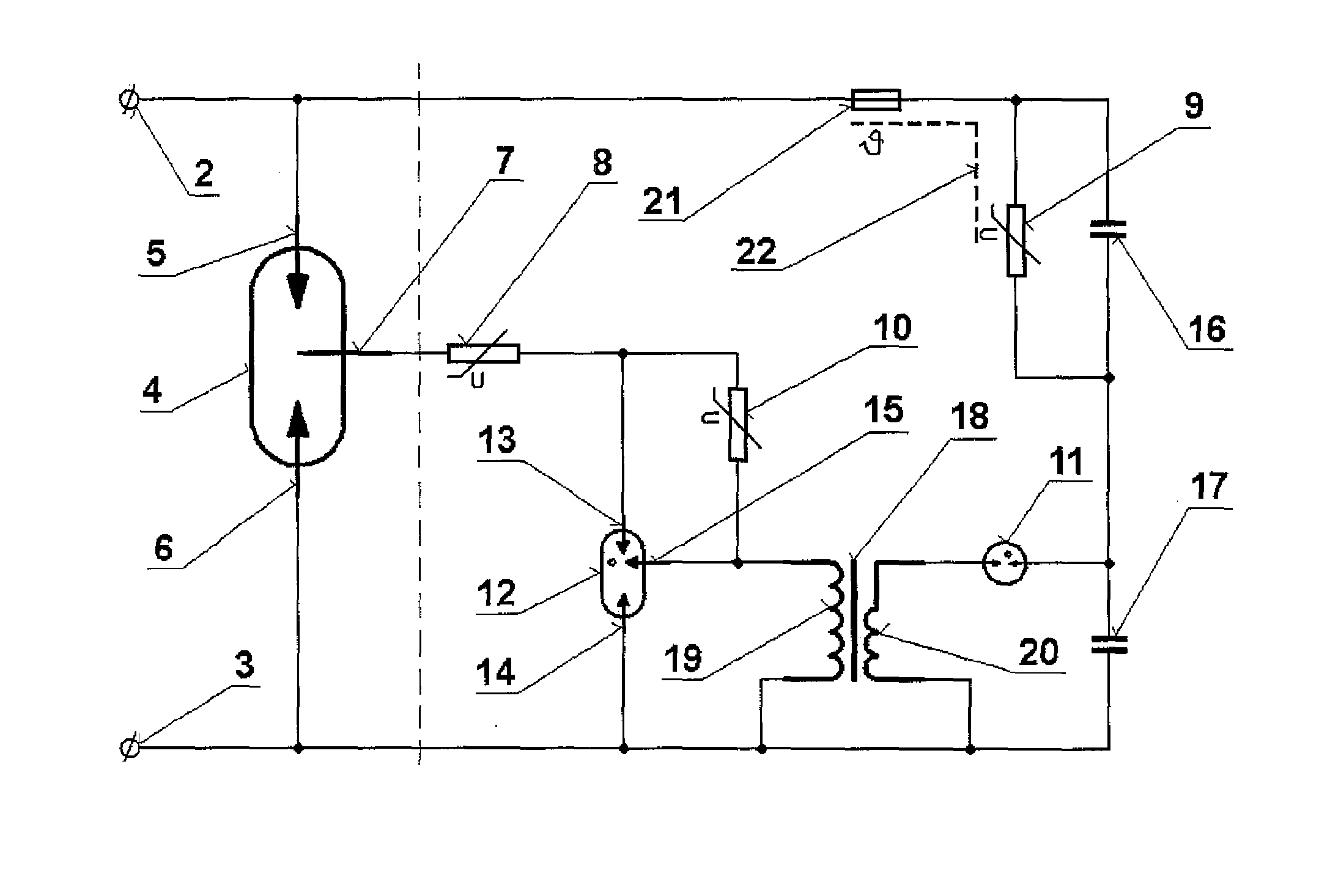
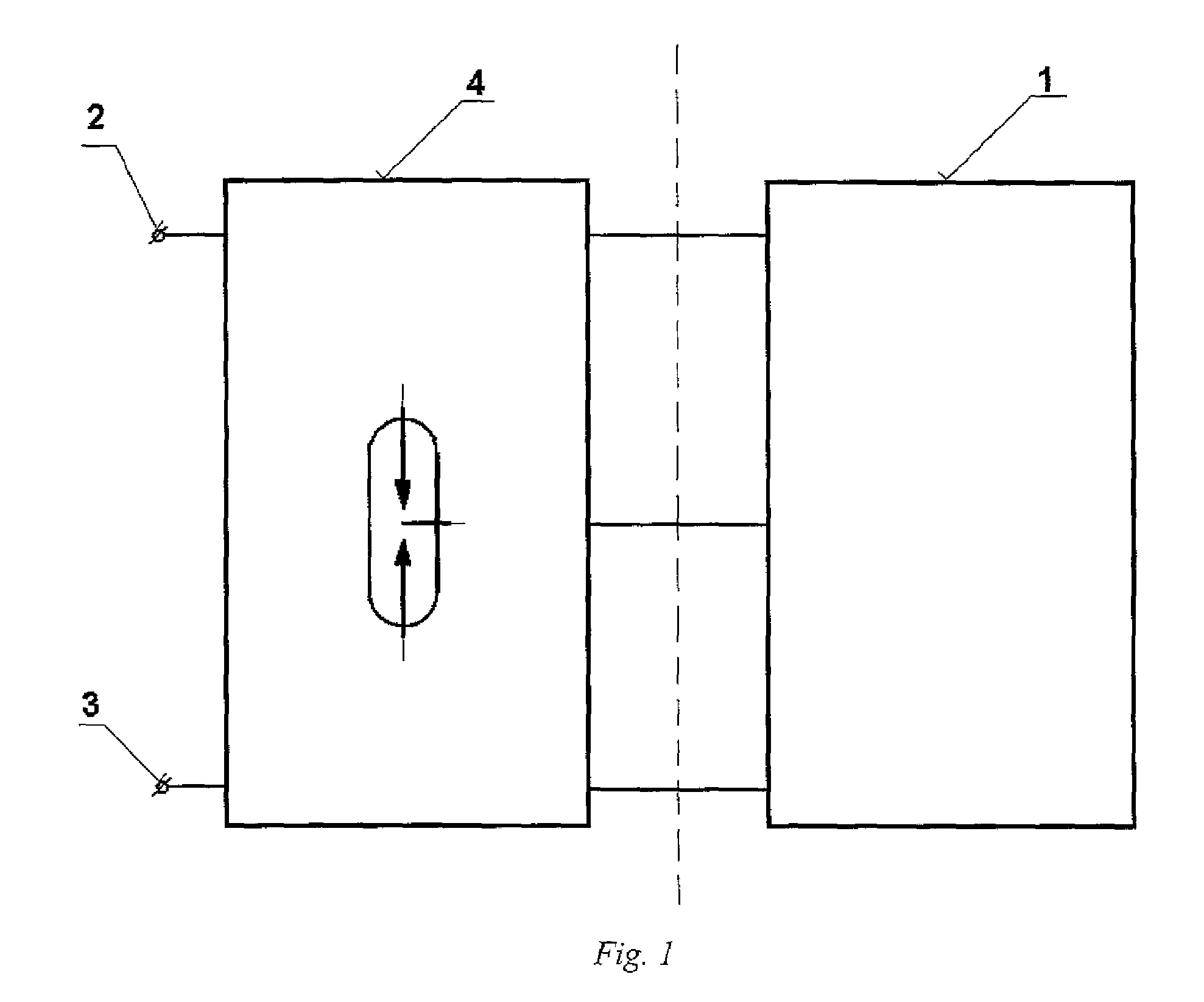
[0026]The wiring diagram of triggering circuit 1 of the overvoltage protection device with an asymmetric element according, to FIG. 1 comprises a spark gap 4 connected to input terminal I 2 and input terminal II 3, whereas triggering circuit 1 of the overvoltage protection device with an asymmetric element is connected in three poles to the spark gap 4.

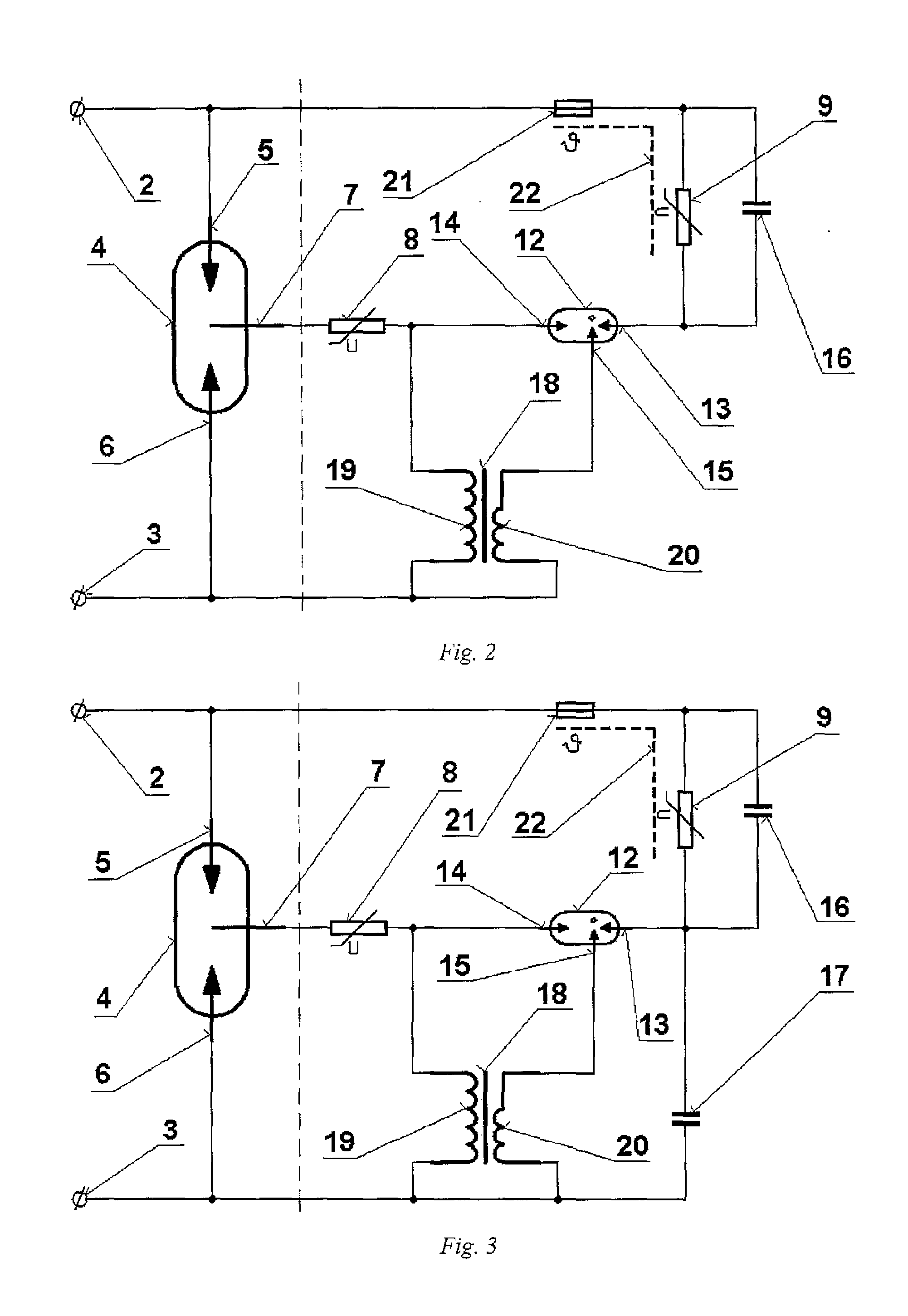
[0027]The design of the triggering circuit 1 of the overvoltage protection device with an asymmetric element according to FIG. 2, specified fir actuating the spark gap 4 in either symmetric or asymmetric arrangement of main electrode I 5, connected to input terminal I 2, main electrode II 6, connected to input terminal II 3, and an auxiliary electrode 7; comprises main electrode I 5 of the spark gap 4, connected via the thermo-sensitive disconnector 21, and also via the parallel combination of varistor II 9 and capacitor I 16 to electrode I 13 of the asymmetric three-pole lightning arrester 12, whose middle electrode 15 is connected v...


PUM


Abstract

A triggering circuit of an overvoltage protection device with an asymmetric element, specified for actuating a spark gap in symmetric or asymmetric arrangement of main electrode I, connected to input terminal I, of main electrode II, connected to input terminal II, and the auxiliary electrode, includes main electrode I of the spark gap, which is connected via a thermo-sensitive disconnector, and also via a parallel combination of varistor II and capacitor I to electrode I of the asymmetric three-pole lightning arrester, whose middle electrode is connected via the primary winding of the transformer to main electrode II of the spark gap, whose auxiliary electrode is connected via varistor I to electrode II of the asymmetric three-pole lightning arrester, which is connected via the secondary winding of the transformer to main electrode II of the spark gap, and at the same time the thermo-sensitive disconnector is coupled via the thermal coupling with varistor II and at the same time, the voltage at the asymmetric three-pole lightning arrester is as follows: static ignition voltage U1 between electrode II and the middle electrode is higher than static ignition voltage U2 between the middle electrode and electrode I.

Description

BACKGROUND AND SUMMARY[0001]The technical solution involves the design of a triggering circuit of overvoltage protection with an asymmetric element representing the area of electrical protection devices designed to restrict overvoltage in a protected distribution network. The overvoltage protection comprises a spark gap connected to input terminal I and input terminal II, whereas a triggering circuit of the overvoltage protection device with an asymmetric element, featuring an asymmetric three-pole arrester, is connected the spark gap in three poles.[0002]Known technical designs of modern lightning arrestors come with an efficient spark gap, equipped with a triggering circuit that quickly actuates the spark gap if impulse overvoltage occurs. Due to its design, the spark gap deactivates quickly, i.e. the flowing follow-on-current is interrupted once the transient overvoltage from the impulse overvoltage has finished. A variety of triggering circuit designs that shall actuate a discha...

Claims


Application Information

Patent Timeline
Patent Type & Authority Applications(United States)
IPC IPC(8): H01T4/02
CPCH01T4/02H01T1/15H01T2/02H02H9/06
Inventor SUCHY, JAROMIR
Owner SALTEK
Features
  • R&D
  • Intellectual Property
  • Life Sciences
  • Materials
  • Tech Scout
  • Unparalleled Data Quality
  • Higher Quality Content
  • 60% Fewer Hallucinations
Learn More