Compaction Method and Device for Automated Fiber Placement

a technology of automatic fiber placement and compacting method, which is applied in the field of methods and equipment, can solve the problems of increasing the layup time and associated costs, difficulty in meeting, and the need for laying up additional tow material on the vertical surface, so as to reduce the non-compacted area, and reduce the waste of material

Active Publication Date: 2016-11-17
THE BOEING CO
View PDF1 Cites 8 Cited by
  • Summary
  • Abstract
  • Description
  • Claims
  • Application Information

AI Technical Summary

Benefits of technology

[0007]The disclosed embodiments provide a method and device for compacting fiber tows on a substrate such as a tool, using automated fiber placement. The device comprises a plurality of compaction rollers mounted for independent movement on a frame forming part of an automated fiber placement head. The use of multiple compaction rollers of smaller diameter, compared to a single larger compaction roller, maintains compaction pressure on the fiber tows at the radius of edge transitions on a layup tool, and in some embodiments may reduce the non-compacted areas of the layup tool to only half of the width of a single one of the tows. The compaction rollers are spring biased to force and compact the fiber tows onto the tool, but may change in attitude (spatial orientation) relative to each other when traversing over an edge between two non-planar tool surfaces in order to maintain contact with the tool and thereby reduce non-compacted areas on the layup. The use of multiple rollers combined with staggered cut / add of the tows at the end of the courses result in a crenulated, near net trim that reduces material waste. The embodiments may reduce layup time and improve part quality by reducing voids caused by non-compaction of fiber tows, and material costs may also be reduced through reduction of scrap.

Problems solved by technology

Difficulties may be encountered when laying up fiber tows along a path forming an angle relative to an edge on the tool.
In the past, this problem has been addressed by making additional passes with the AFP machine over the non-compacted areas, however this approach increases the layup time and associated costs.
Another problem associated with using a single compaction roller is the need for laying up additional tow material on the vertical surface in those part applications where an edge of the part falls below a minimum layup distance beyond the area of non-compaction.
The use of multiple rollers combined with staggered cut / add of the tows at the end of the courses result in a crenulated, near net trim that reduces material waste.

Method used


Image

  • Compaction Method and Device for Automated Fiber Placement
  • Compaction Method and Device for Automated Fiber Placement
  • Compaction Method and Device for Automated Fiber Placement

Examples


Embodiment Construction

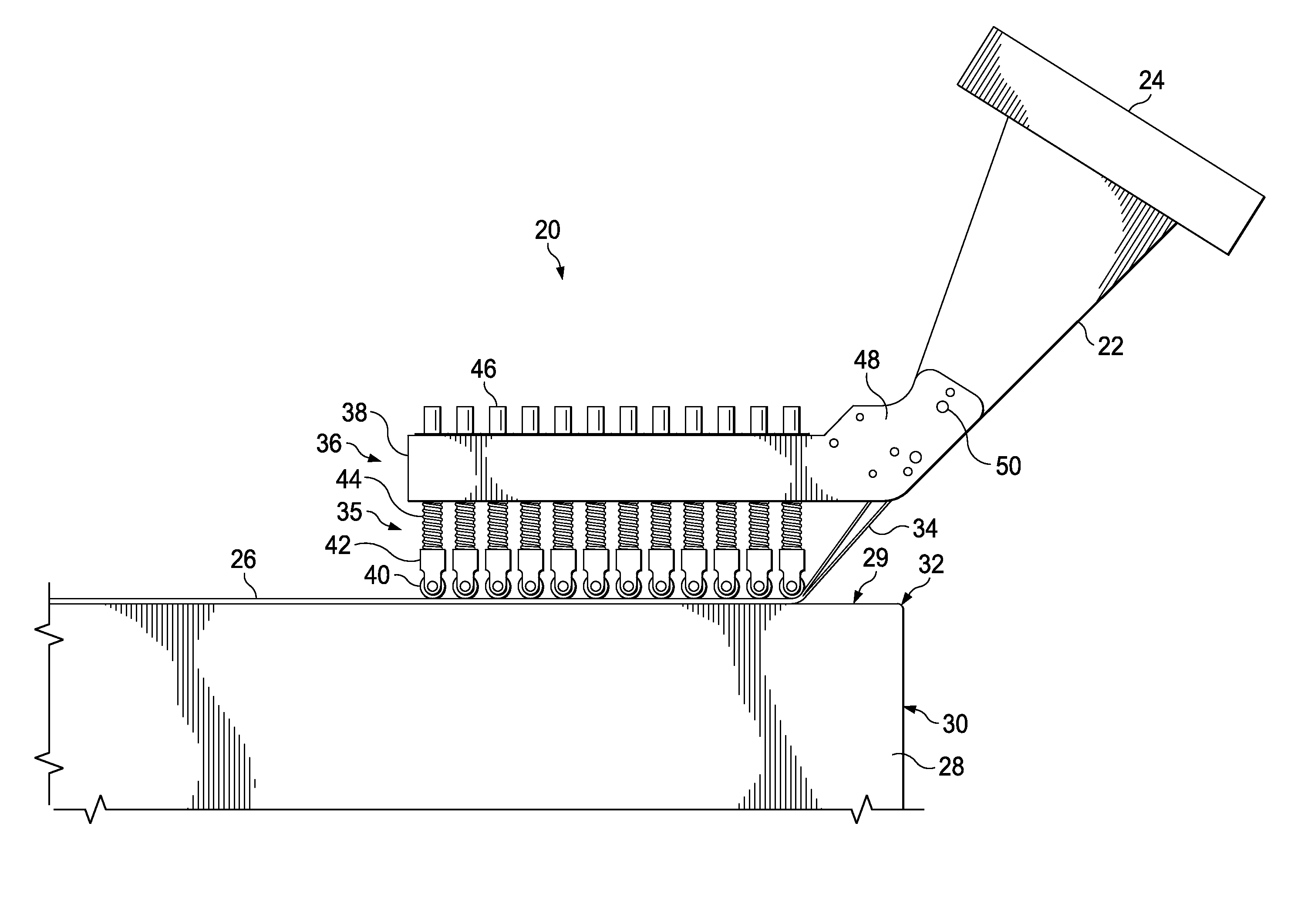
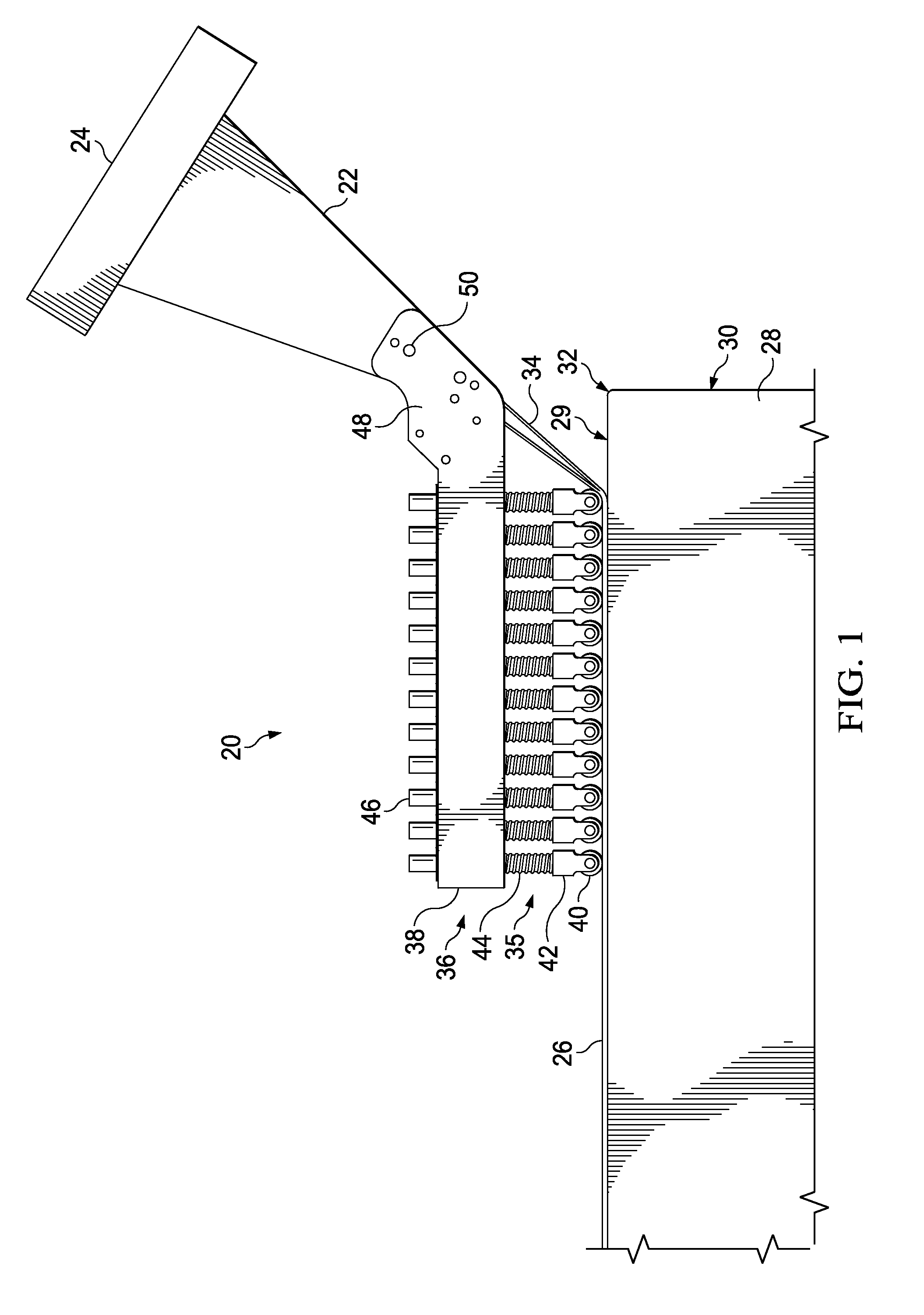
[0029]Referring first to FIG. 1, an AFP head 22 is mounted on an adapter 24 coupled with a robot (not shown) or similar digital numerically controlled manipulator for laying up composite parts on a tool 28. The AFP head 22 includes a compaction device 20 that is adapted to compact pre-impregnated fiber tows 34 which are fed from and cut to length by the AFP head 22. The fiber tows 34 are laid up in side-by-side relationship, forming a conformal bandwidth 26 of the fiber tows 34. In one embodiment, the fiber tows 34 may comprise slit prepreg tape, however principles of the disclosed embodiments are also applicable to automated tape layup (ATL) in which full width tape is laid down and compacted by the compaction device 20.

[0030]The embodiments are well-suited to laying up composite parts on a tool 28 having undulating surfaces or surfaces lying in different planes joined along an edge where traversing the edge with a single compaction roller may result in a portion of the roller lift...


PUM

PropertyMeasurementUnit
angleaaaaaaaaaa
widthaaaaaaaaaa
angleaaaaaaaaaa

Abstract

A compaction device for use with an automated fiber placement machine includes multiple compaction rollers mounted for independent displacement on a supporting frame. The attitude of the compaction rollers change relative to each other when fiber tows are laid up at an angle over an edge of a tool in order to maintain compaction pressure on the tows and thereby reduce non-compacted areas of the tows.

Description

BACKGROUND INFORMATION[0001]1. Field[0002]The present disclosure generally relates to methods and equipment for laying up composite parts using automated fiber placement, and deals more particularly with a method and device for compacting fiber tows, particularly fiber tows having angular fiber orientations.[0003]2. Background[0004]Automated fiber placement (AFP) machines are used in various industries to layup composite parts, particularly small parts and / or those having complex geometries, to increase rate and precision. AFP machines place a bandwidth of fiber tows on a layup tool such as a mold tool or layup mandrel. The fiber tows may be in the form of split tape, and may comprise thermoset or thermoplastic pre-impregnated unidirectional fiber reinforcements that are laid up in various fiber orientations e.g., 0°, + / −45°, + / −60°, 90°. A bandwidth of the tows are dispensed, cut to length and compacted onto the tool by an AFP head that is typically automatically controlled by a nu...

Claims


Application Information

Patent Timeline
Patent Type & Authority Applications(United States)
IPC IPC(8): B29C70/38B29C65/00B29C65/02
CPCB29C70/384B29C66/81453B29C66/8362B29C65/02
Inventor CHAPMAN, MICHAEL ROBERTWATSON, ROBERT M.WILLIAMS, STEPHEN HOWARD
Owner THE BOEING CO
Why Eureka
Try Eureka