
Upper vehicle-body structure of vehicle

a vehicle and upper body technology, applied in the direction of vehicle components, superstructure subunits, transportation and packaging, etc., can solve the problems of rusting on the inner face of the frame, the performance of the reinforcing member for suppressing the deformation of the frame section cannot be confirmed in manufacturing, and the inability to achieve the expected performance of the reinforcing member for suppressing the deformation of the frame section, etc., to achieve the effect of improving the vehicle-body strength

Active Publication Date: 2016-11-17
MAZDA MOTOR CORP
View PDF0 Cites 10 Cited by
  • Summary
  • Abstract
  • Description
  • Claims
  • Application Information

AI Technical Summary

Benefits of technology

The present invention is an upper vehicle-body structure that improves the vehicle-body strength and ensures manufacturing quality. It includes a pillar member, a roof side rail, and a synthetic resin-made reinforcing member. The reinforcing member is provided inside the roof side rail and has a gap from the outer member. The reinforcing member is integrally joined to the inner member of the roof side rail by the anchor effect, allowing for proper fixing and manufacturing tolerance. This structure suppresses buckling and ensures a safe and reliable vehicle body.

Problems solved by technology

However, this structure has the following problems.
First, it cannot be confirmed in manufacturing whether or not the reinforcing members and respective inside faces of the frames are joined together by the foamable resin without any gap formed therebetween.
Secondly, when the frames are deformed by an external force, adhesion portions with the foamable resin are destroyed in an early stage and thereby separate moves of the frames and the reinforcing members are allowed, so that the performance of the reinforcing members for suppressing deformation of frame sections cannot be obtained as expected.
Thirdly, the foaming agent blocks smooth flowing of electrodeposition liquid inside the frames, so that rusting is induced on an inner face of the frames.

Method used


Image

  • Upper vehicle-body structure of vehicle
  • Upper vehicle-body structure of vehicle
  • Upper vehicle-body structure of vehicle

Examples


Embodiment Construction

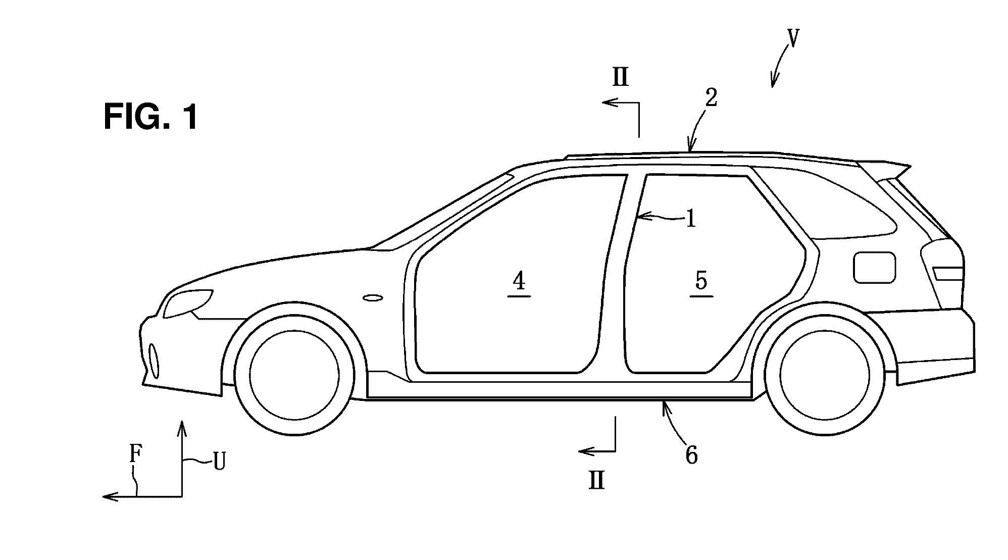
[0033]Hereafter, embodiments of the present invention will be described referring to the accompanying drawings. The following description exemplifies the present invention applied to a vehicle V, and applications or uses of the present invention are not to be limited. In figures, an arrow F shows a forward direction, an arrow L shows a leftward direction, and an arrow U shows an upward direction.

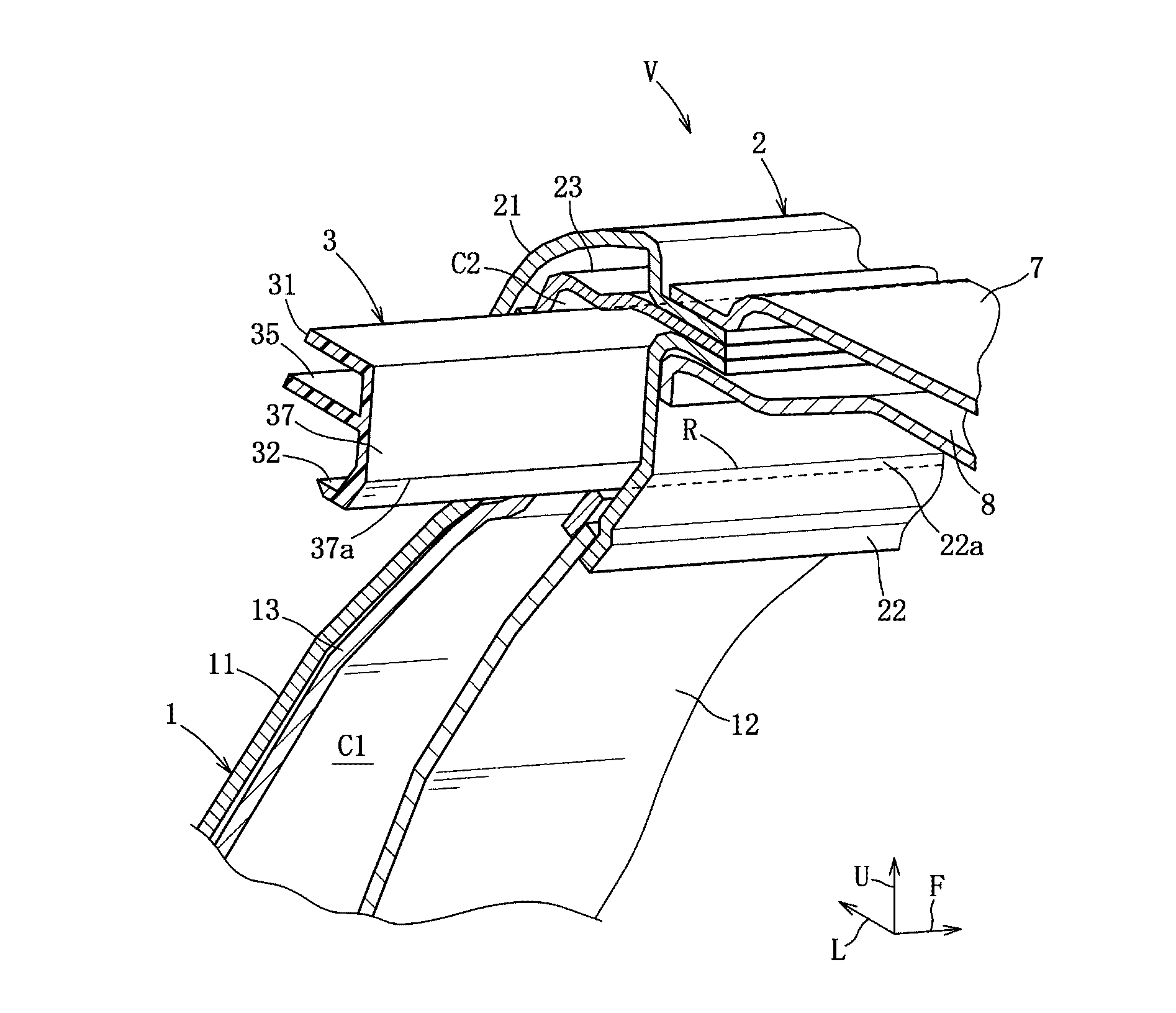
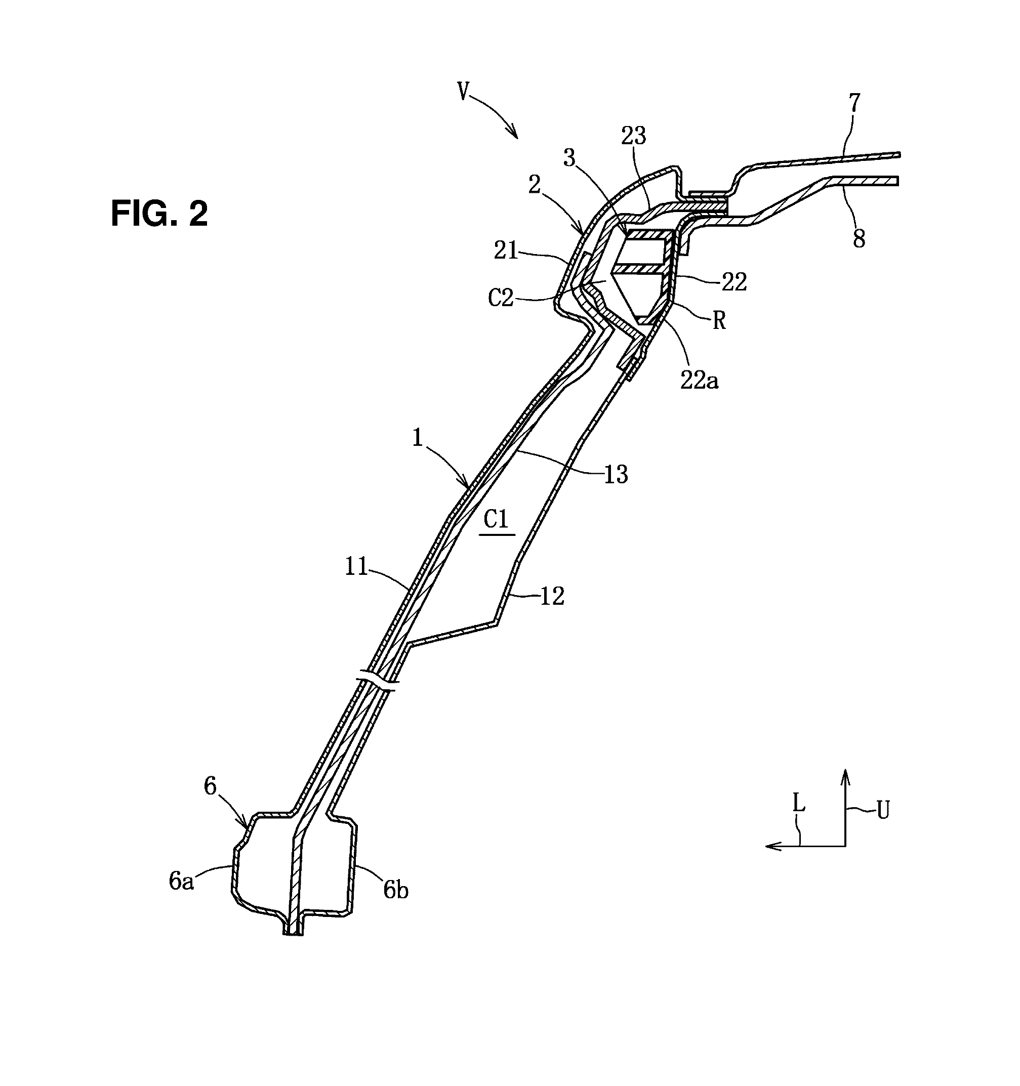
[0034]Hereafter, an embodiment of the present invention will be described referring to FIGS. 1-12. As shown in FIGS. 1-3, the vehicle V comprises a pair of right-and-left center pillars 1 (pillar member) which extend in a vertical direction, a pair of right-and-left roof side rails 2 which connect to respective upper end portions of the pair of center pillars 1 and extend in a vehicle longitudinal direction, a pair of right-and-left synthetic resin-made reinforcing members 3 which are provided inside the pair of roof side rails 2, and others. Herein, the vehicle V has a symmetrical structure...


PUM


Abstract

There are provided a center pillar, a roof side rail connected to an upper end portion of the center pillar and having a closed cross section extending in a vehicle longitudinal direction, and a synthetic resin-made reinforcing member provided inside the roof side rail at a position near an upper end portion of the center pillar. The roof side rail comprises a roof rail inner having a protrusion portion and a roof rail outer forming the closed cross section together with the roof rail inner. The reinforcing member is provided to have a gap from the roof rail outer and integrally joined to an outward face, in a vehicle width direction, of the roof rail inner which is roughened by an anchor effect.

Description

BACKGROUND OF THE INVENTION[0001]The present invention relates to an upper vehicle-body structure of a vehicle, and particularly relates to the upper vehicle-body structure of the vehicle comprising a synthetic resin-made reinforcing member provided inside a roof side rail.[0002]A structure of the vehicle in which the reinforcing member for improving the vehicle-body rigidity is provided in a closed cross section of a frame is known because the vehicle requires the collision safety, the maneuverability and stability, and the silence.[0003]Japanese Patent Laid-Open Publication No. 2001-191947 discloses an upper vehicle-body structure which comprises a hard synthetic resin-made first reinforcing member which is provided inside a center pillar and a hard synthetic resin-made second reinforcing member which is provided inside a roof side portion for the purpose of increasing the strength against a vehicle side collision.[0004]In the upper vehicle-body structure of the above-described pa...

Claims


Application Information

Patent Timeline
Patent Type & Authority Applications(United States)
IPC IPC(8): B62D29/00B62D25/06B62D25/04
CPCB62D29/001B62D25/06B62D25/04B62D29/005
Inventor OKUYAMA, TOMOHITOKODAMA, YUKIHADA, TETSUNORI
Owner MAZDA MOTOR CORP
Learn More