Tile spacing device and method of use

a technology of spacers and tiles, applied in the field of tile spacers, can solve the problems of lost spacers, broken tiles and irretrievable time, and affecting the life of homeowners, and achieve the effect of convenient means of switching

Inactive Publication Date: 2016-11-17
KUDRNA JOHN R
View PDF15 Cites 2 Cited by
  • Summary
  • Abstract
  • Description
  • Claims
  • Application Information

AI Technical Summary

Benefits of technology

[0013]It is another object of the present invention to provide spacers available in ...

Problems solved by technology

This causes an installer to juggle tiles and spacers leading to frustration, lost spacers, broken tile and irretrievable time.
While...

Method used


Image

  • Tile spacing device and method of use
  • Tile spacing device and method of use
  • Tile spacing device and method of use

Examples


Embodiment Construction

[0021]The main purpose behind this device, nicknamed the “Kelly Gauge”, is to provide consumers (either professional tile installers or do-it-yourselfers) with a tool that facilitates the process for maintaining accurate spacing between adjacent tiles during their initial installation (i.e., as they are first positioned on the setting mortar). This is a known time-consuming task made longer when expending a great deal of effort calculating tile spacing AND placement to avoid uneven relative positioning.

[0022]This device replaces the use of small plastic spacer crosses and the like. Workers using those means are often forced to recheck their gapping measurements as smaller spacers are prone to shifting.

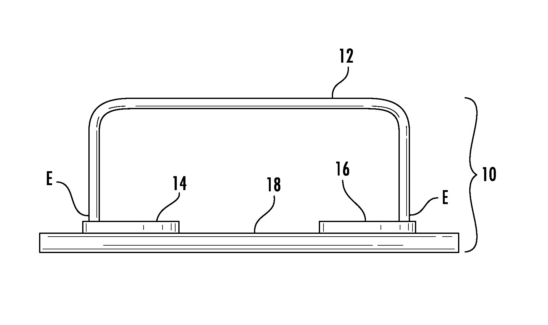
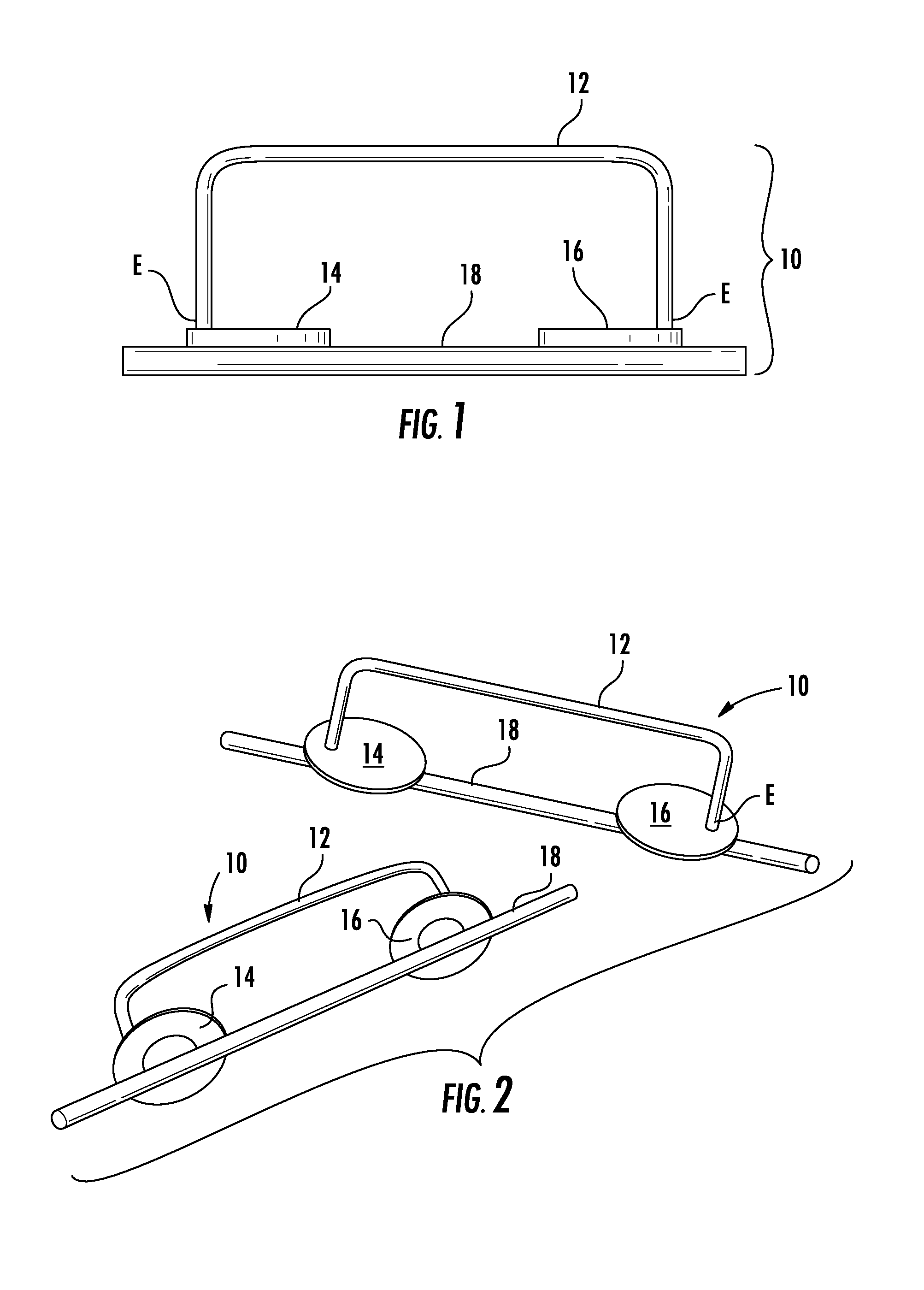
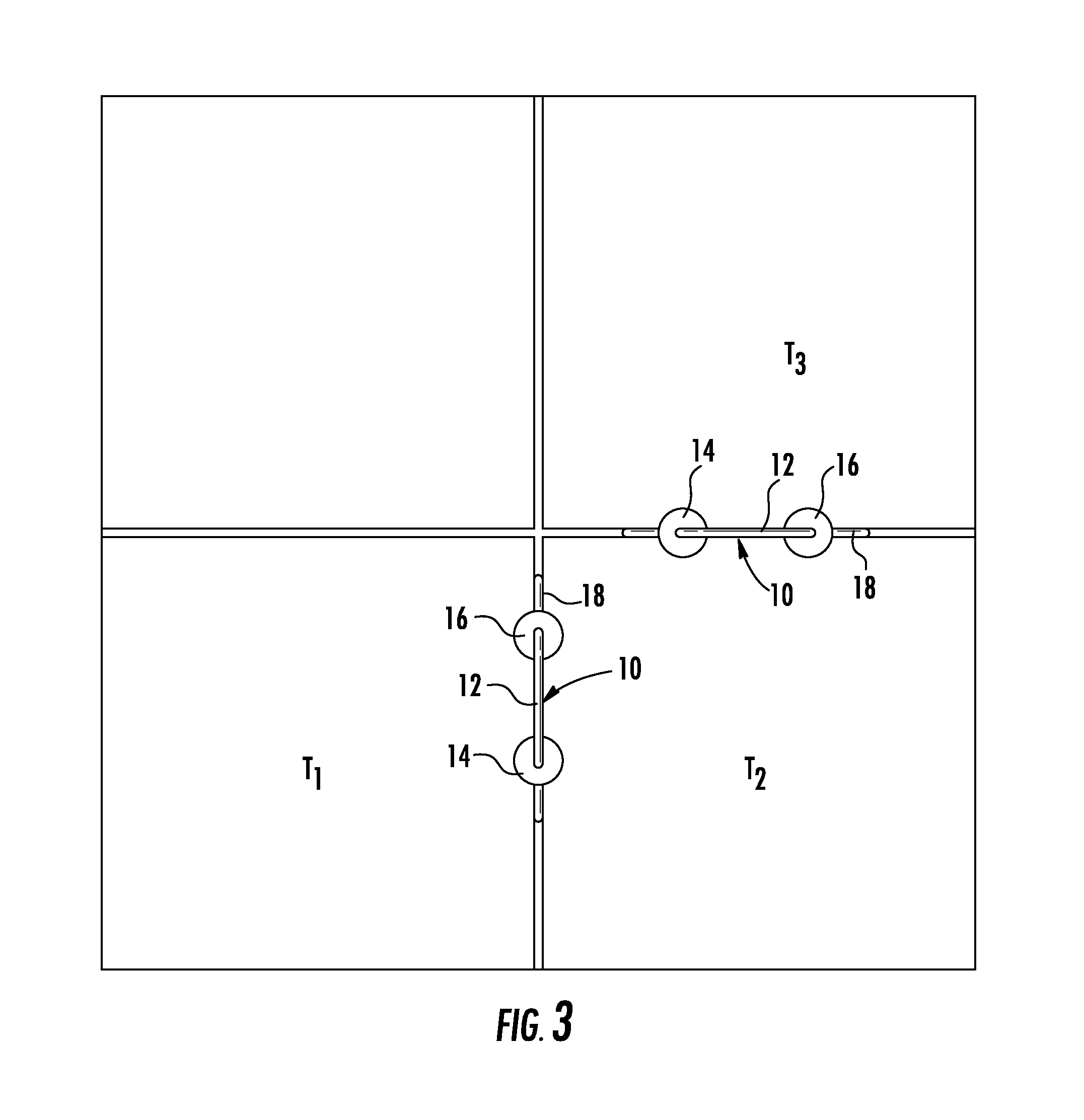
[0023]The present device, by contrast, is an ingenious, practical and useful (yet simple) tool for gauging grout spacing between tiles quickly and easily. As seen in accompanying FIGS. 1 and 2, one embodiment of tile spacer device 10 that includes a main frame, in this case consisting ...


PUM


Abstract

A tile spacing device comprises a U-shaped handle, a pair of washers affixed to both open ends of the handle; and a gap-creating spacer bar extending between the open handle ends beneath the pair of washers. A method of using this device for improving spacing consistency between horizontally-installed tiles is also disclosed.

Description

BACKGROUND OF THE INVENTION[0001]1. Field of the Invention[0002]This invention relates to a device for setting decorative tiles with uniform grout lines and joints. More particularly, it relates to a tile spacer for efficiently setting a plurality of large decorative floor tiles a uniform, consistent width from adjacent tiles.[0003]2. Description of the Related Art[0004]Anyone who has ever installed tile products understands the aggravation with adjusting tiles, especially floor tiles, during installation, to maintain uniform grout lines and joints. The spacing between each piece allows for the eventual placement of grout there between. Known plastic spacers can be set to aid in this process, but they must be moved individually when the next piece is to be installed. This causes an installer to juggle tiles and spacers leading to frustration, lost spacers, broken tile and irretrievable time. While these problems are difficult for the professional tile setter, they pose almost insurm...

Claims


Application Information

Patent Timeline
IPC IPC(8): E04F21/00
CPCE04F21/0076E04F21/0092
Inventor KUDRNA, JOHN R.
Owner KUDRNA JOHN R
Why Eureka
Try Eureka