Device for measuring the travelling speed of a fluid in relation to an object

a technology of fluid travelling speed and measuring device, which is applied in the direction of measuring device, volume/mass flow measurement, instruments, etc., can solve the problems of affecting the local aerodynamic or hydrodynamic instability of elements

Inactive Publication Date: 2016-11-17
POLYVIONICS
View PDF1 Cites 7 Cited by
  • Summary
  • Abstract
  • Description
  • Claims
  • Application Information

AI Technical Summary

Benefits of technology

[0023]In particular, the computer is capable of performing the following tasks: interfacing with the at least one sensor for importing the latter's measurements; preliminary processing of the data by means of Kalman filtration, a low-pass filter, a sliding polynomial linear regressor; determination of the Fourier transform and the spectral densities of the induced instabilities.

Problems solved by technology

In particular, the element generating local aerodynamic or hydrodynamic instability is attached to the object.

Method used


Image

  • Device for measuring the travelling speed of a fluid in relation to an object
  • Device for measuring the travelling speed of a fluid in relation to an object
  • Device for measuring the travelling speed of a fluid in relation to an object

Examples


first embodiment

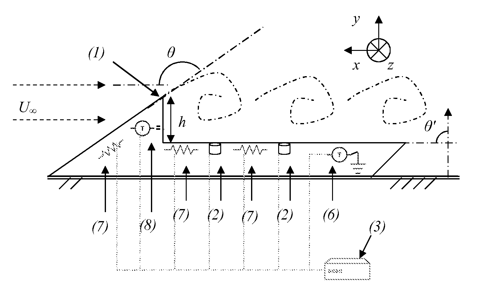
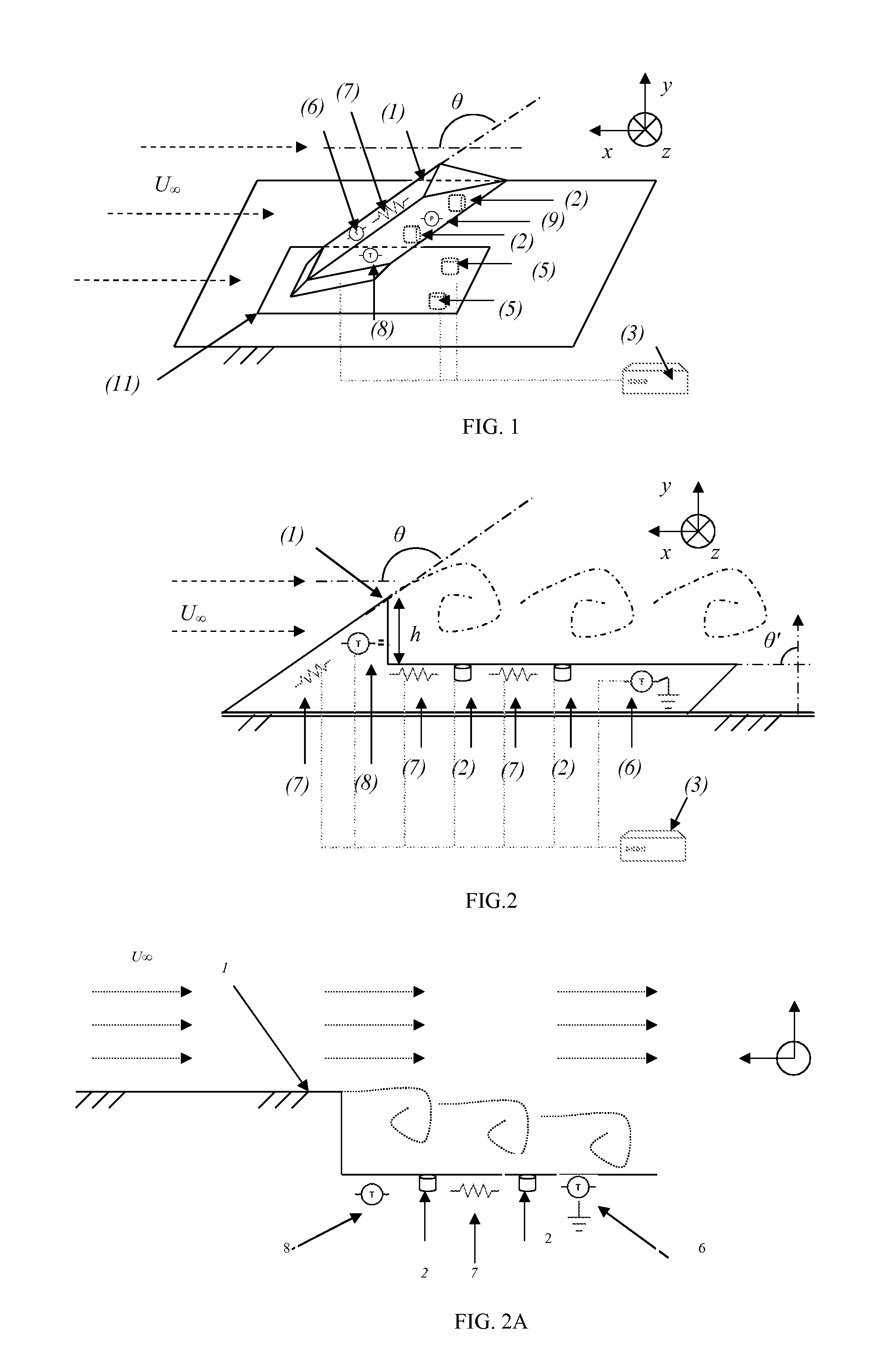
[0048]According to the invention, the local aerodynamic or hydrodynamic instability may be induced naturally by an element 1, native or intrinsic to the object. For instance, a fuselage, airfoil, tailplane or fin element, etc. in the case of an aerial mobile. When the object is a land vehicle, a bodywork element may act as a generator of the local aerodynamic or hydrodynamic instability. Hence, a hull element, in the case of a marine / river vehicle; an elbow, bend element, etc., for a duct; a pole element for a weather station, may generate local aerodynamic or hydrodynamic instability.

[0049]Furthermore, the element 1, generating local aerodynamic or hydrodynamic instability, may be an obstacle or a cavity already present on the object where it performs a specific function; for example, a Pitot tube, and alpha / beta probe, an antenna in the case of an aerial mobile; a rear view mirror, an antenna, . . . for a land vehicle.

[0050]The element 1, generating local aerodynamic or hydrodynam...

third embodiment

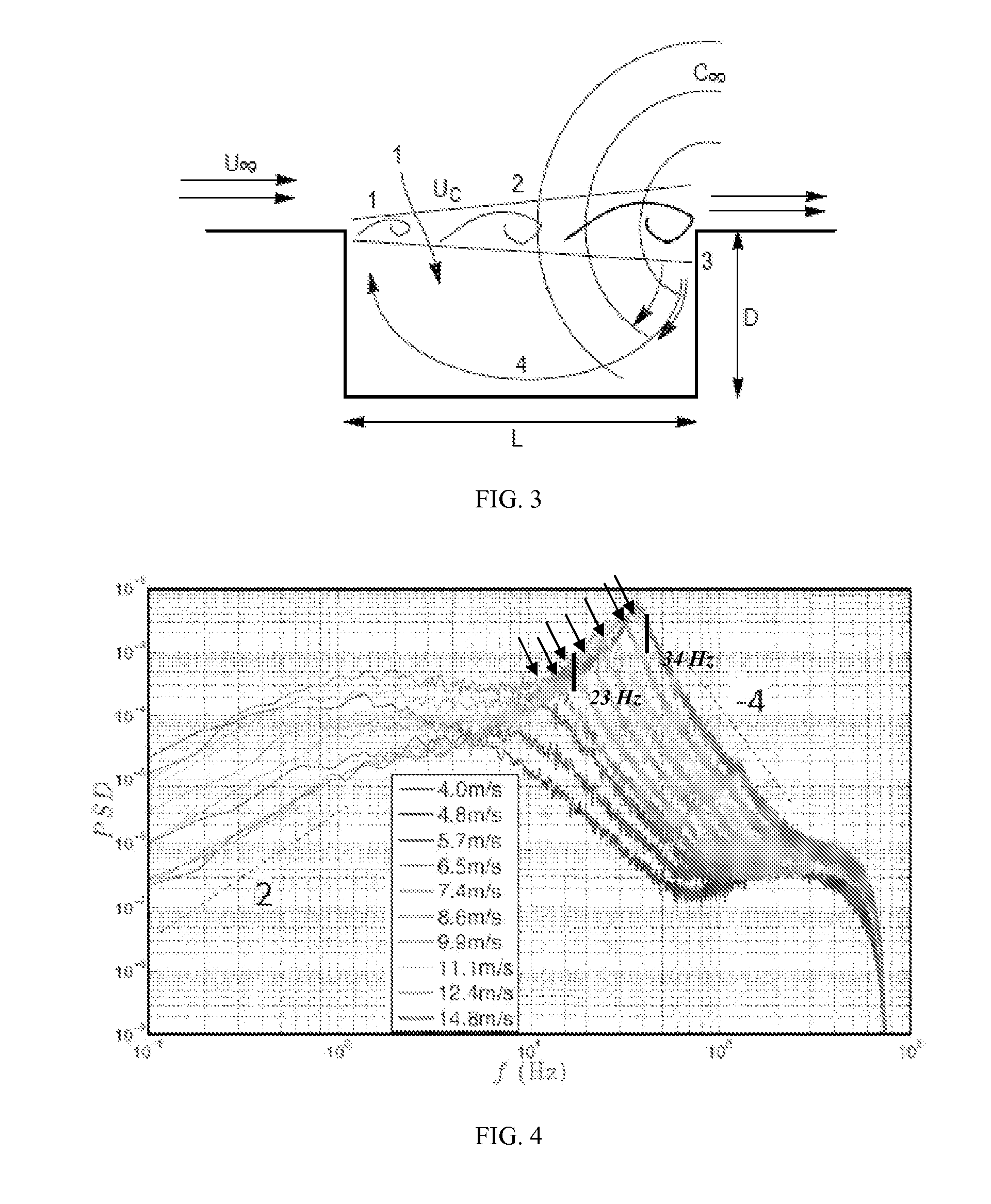
[0099]With reference to FIGS. 6A and 6B, the invention involves a body 40 specifically developed to be situated in the fluid flow and generate instabilities by means of a cavity 1. The instabilities are measured by instability sensors 2 placed inside said cavity 1. The body 40 is positioned in the relative flow of the fluid. Said body 40 is metallic and hollow in order to contain elements specific to the invention. The cavity 1 is open towards the outside (one single opening) of the body 40 and is arranged such that the fluid can enter its inside. The body 40, in addition to the cavity 1, may be executed as a machined block or in several parts. The body 40 adopts a pseudo-triangular shape in the XY plane (“ramp” type), so as not to have any stagnation point, in order not to retain ice. The downstream wall of the cavity 1 has a dimension along the Y axis greater than that of its upstream wall. The downstream wall slopes in relation to the YZ plane in order to allow any crystals conta...


PUM


Abstract

Device for measuring the relative speed of movement of a fluid in relation to an object, characterised in that said device comprises at least one sensor 2 positioned in a suitable area of the object, wherein said at least one sensor 2 is capable of identifying and utilising, in conjunction with at least one computer 3, local aerodynamic or hydrodynamic instability, originating from the relative movement of said fluid in relation to an element 1 of said object, depending on the speed of movement of the fluid. The device is characterised in that said element 1 is an obstacle or a hollow cavity with a single opening contained in a body 40 and open towards the outside of said body, wherein said body is positioned on the object, the relative velocity of the fluid of which one wishes to ascertain, such that said cavity 1 is skimmed by the fluid and in that said at least one aerodynamic/hydrodynamic instability sensor 2 utilises the process of self-oscillation of the fluid inside the cavity 1 in order to determine the fluid's relative speed of movement.

Description

TECHNICAL FIELD OF THE INVENTION[0001]The invention relates to a system capable of measuring the speed of movement of a fluid in relation to an object. Said object may for example be an aerial, terrestrial, marine or space mobile, etc., a wind tunnel, a turbine engine, a duct or a weather station.PRIOR STATE OF THE ART[0002]In aeronautics and likewise in other technical fields, the velocity of a fluid in relative flow (airspeed of an aircraft for example) is commonly measured using a Pitot tube. This tube measures the static or ambient pressure in addition to the total pressure, created by the impact of the fluid on a capsule and subsequently calculates the aircraft's airspeed based on an algorithm.[0003]In a number of cases however, the Pitot tube may be subject to blockage, icing for instance in the case of an aircraft owing to its flight altitude, to atmospheric pressure, to environmental temperature and humidity, to the crystals contained in clouds and to the air stagnation poin...

Claims


Application Information

Patent Timeline
Patent Type & Authority Applications(United States)
IPC IPC(8): G01F1/66
CPCG01F1/662G01P5/14
Inventor QUERRY, STEPHANE LUC SEBASTIEN
Owner POLYVIONICS
Why Eureka
Try Eureka