

Inrush current suppression circuit
- Summary
- Abstract
- Description
- Claims
- Application Information
AI Technical Summary
Benefits of technology
Problems solved by technology
Method used
Image

Examples
Embodiment Construction
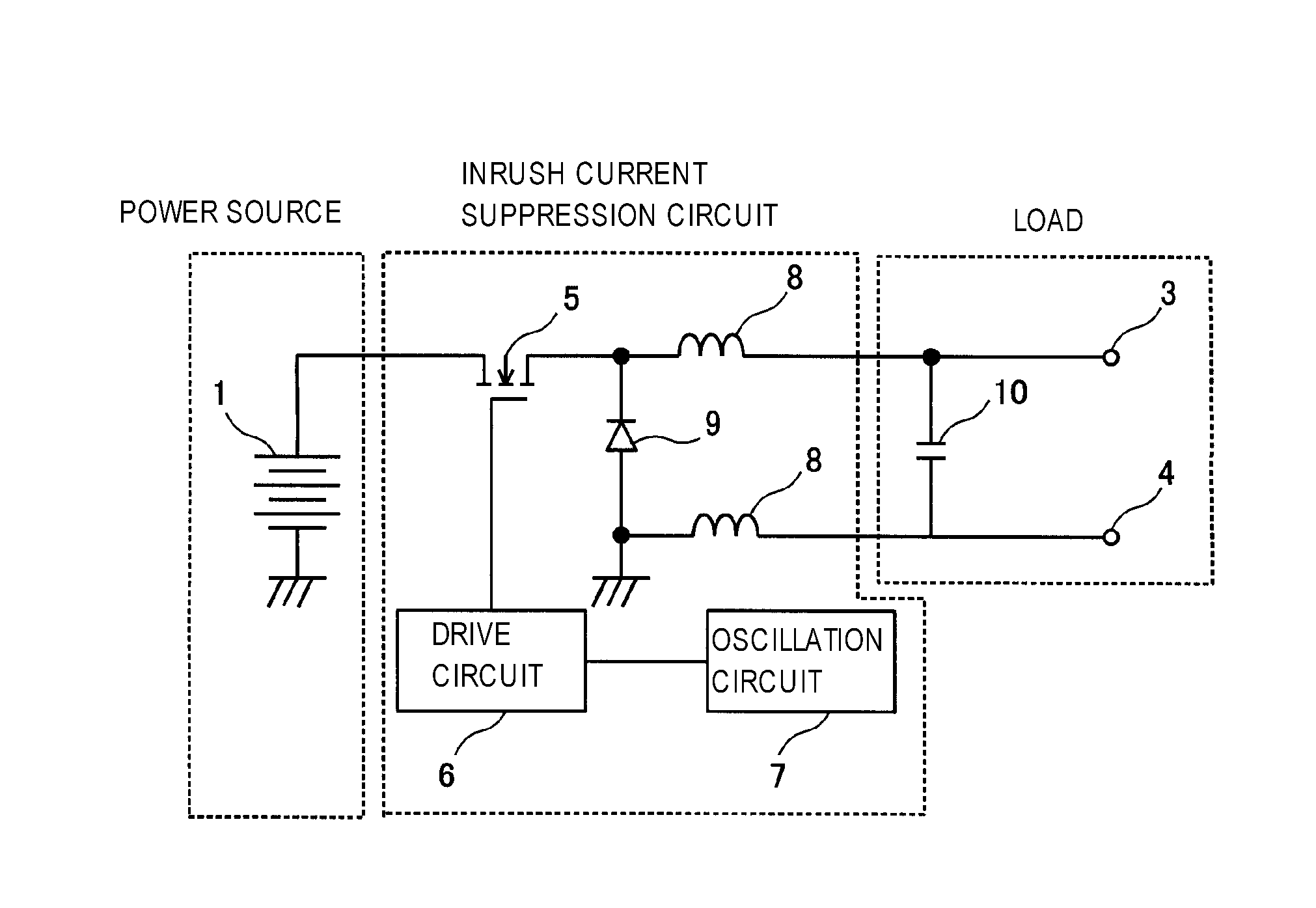
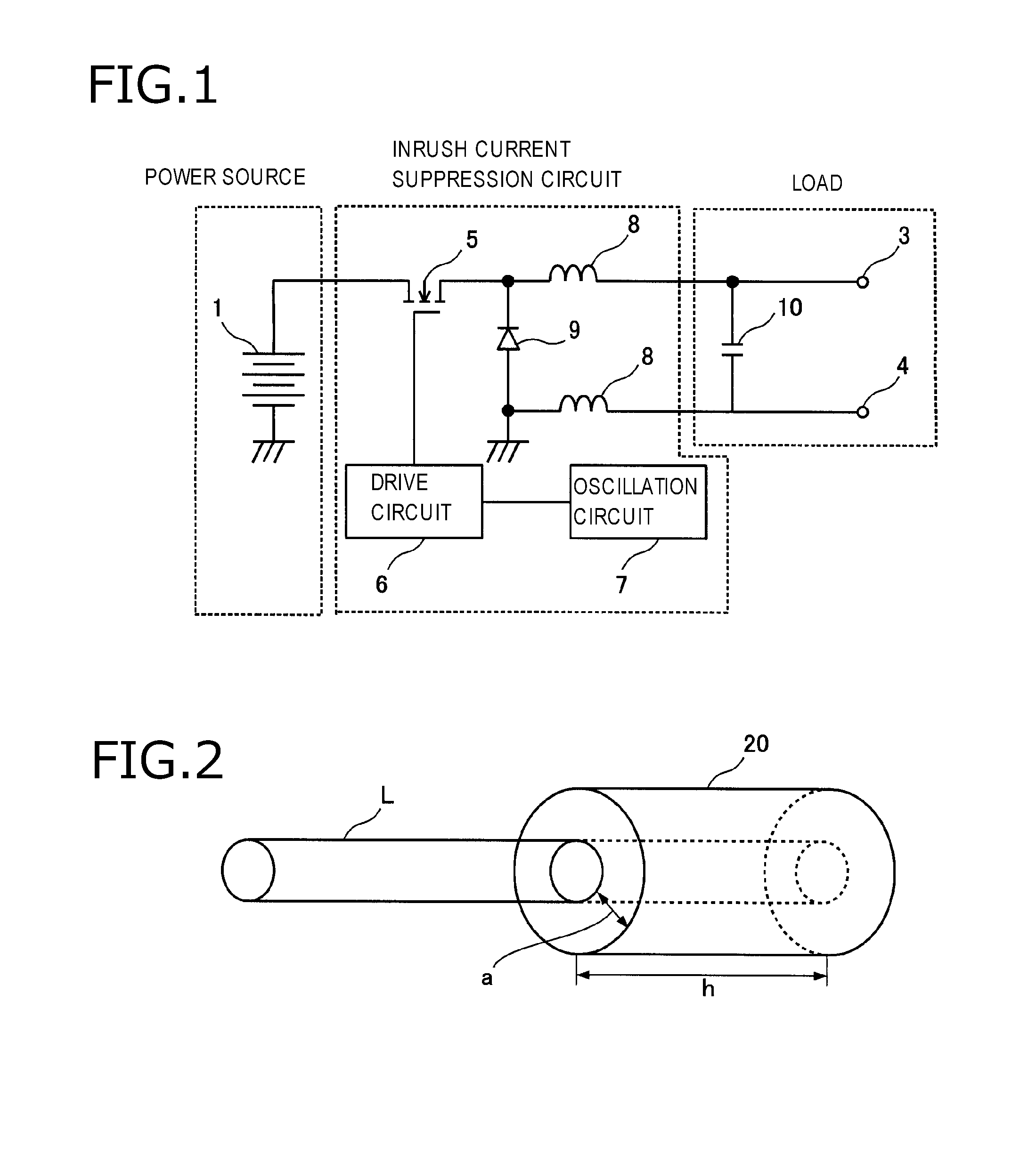
[0018]FIG. 1 is a circuit diagram showing the configuration of an inrush current suppression circuit according to an embodiment. The inrush current suppression circuit according to the embodiment serves to output power to a load receiving an input from a DC power source 1 and suppresses an inrush current to flow from the DC power source 1 (e.g., battery) to the load. The inrush current suppression circuit mainly includes an FET 5, first and second inductors 8, and a free wheel diode 9.
[0019]The load includes an input capacitor 10 and a pair of output terminals 3 and 4 and is an inverter, for example.
[0020]The input capacitor 10 is connected to the DC power source 1 via the inrush current suppression circuit and is disposed on the input side of the pair of output terminals 3 and 4.
[0021]The pair of output terminals 3 and 4 are parallel-connected to the input capacitor 10 and outputs an input current supplied from the DC power source 1. A load element (not shown) is connected between ...
PUM
 Abstract
Description
Claims
Application Information