Fluidic connector for negative pressure wound therapy

a technology of negative pressure and wound therapy, applied in the direction of dressings, other medical devices, intravenous devices, etc., can solve the problems of delayed wound healing, adverse affecting the healing process, and damage to the wound site,

Active Publication Date: 2016-11-24
SMITH & NEPHEW INC
View PDF20 Cites 134 Cited by
  • Summary
  • Abstract
  • Description
  • Claims
  • Application Information

AI Technical Summary

Benefits of technology

[0015]In some embodiments the reinforcement is configured to be positioned between the top surface of the cover layer and the lower surface of the fluidic connector. The lower surface of the fluidic connector may be configured to be adhered to the reinforcement. The reinforcement may be positioned between the top surface of the cover layer and the lower surface of the elongate conduit. In some embodiments the reinforcement may comprise a strip of adhesive tape. The strip of adhesive tape may be configured to be positioned between the sealing surface and an edge of the cover layer. In some embodiments the reinforcement may comprise a skirt configured to be positioned between the sealing surface and the top surface of the cover layer. The skirt may comprise an opening configured to be positioned over the aperture in the cover layer. In some embodiments the sealing surface is adhered to the top surface of the cover layer with a first adhesive, and the lower surface of the fluidic connector is adhered to the reinforcement with a second adhesive. The first adhesive may be an adhesive ring that surrounds the aperture in the cover layer, and the second adhesive may be one of a second adhesive ring surrounding the first adhesive ring and an adhesive layer on a lower surface of the elongate conduit. The reinforcement may be provided over the fluidic connector. The reinforcement provided over the fluidic connector may be an adhesive tape provided over the elongate con

Problems solved by technology

The stiffness of certain suction ports in such close proximity to the wound site can adversely affect the healing process.
Such force can cause disturbance of a wound bed which can damage a wound site.
This can potentially cause delays in healing of the wound site and discomfort for the patient.
The tubing may become obstructed by movement of the patient, which may cause the tube to bend and form a kink or may place pressure onto the tubing, substantially or fully blocking the flow of fluid through the tubing.
This can reduce or eliminate the negative pressure being transmitted to the wound site, and in embodiments employing a separate canister for fluid collection it can also resul

Method used


Image

  • Fluidic connector for negative pressure wound therapy
  • Fluidic connector for negative pressure wound therapy
  • Fluidic connector for negative pressure wound therapy

Examples


Embodiment Construction

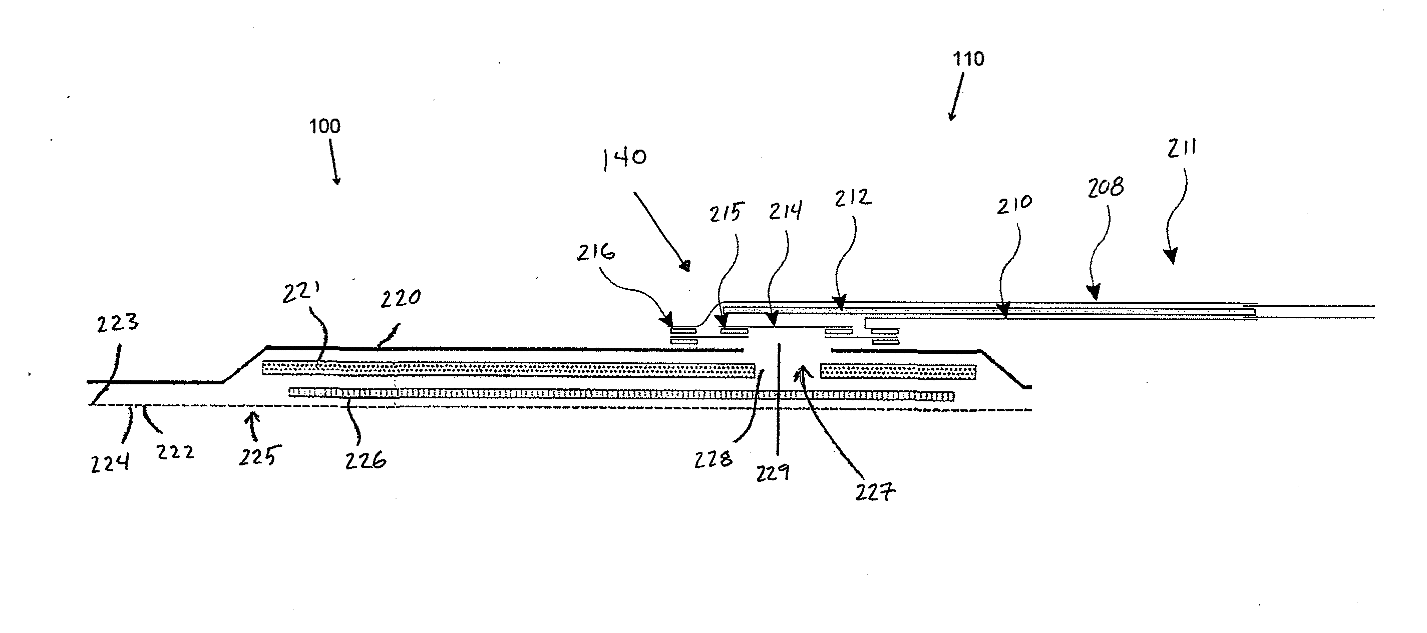
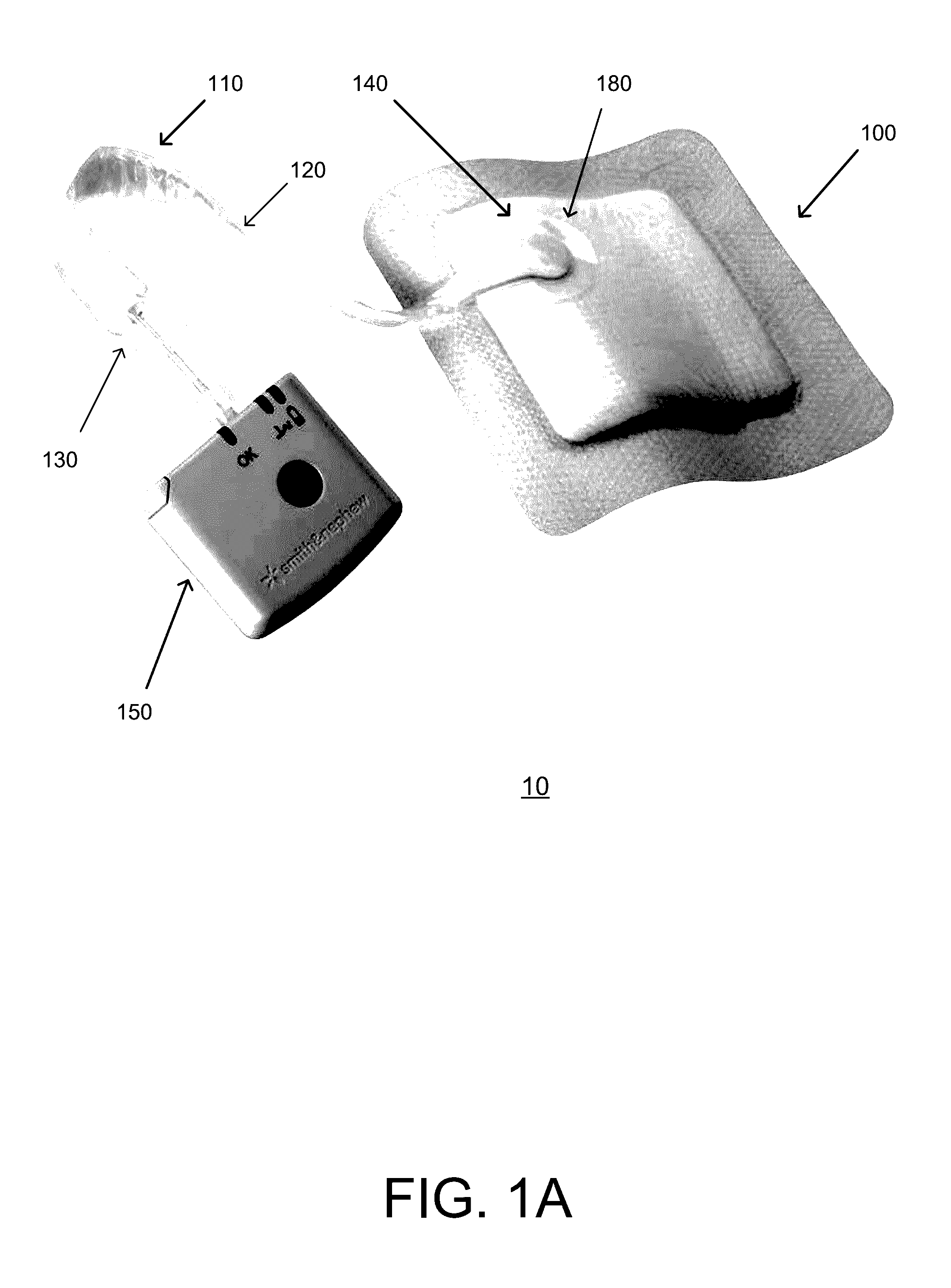
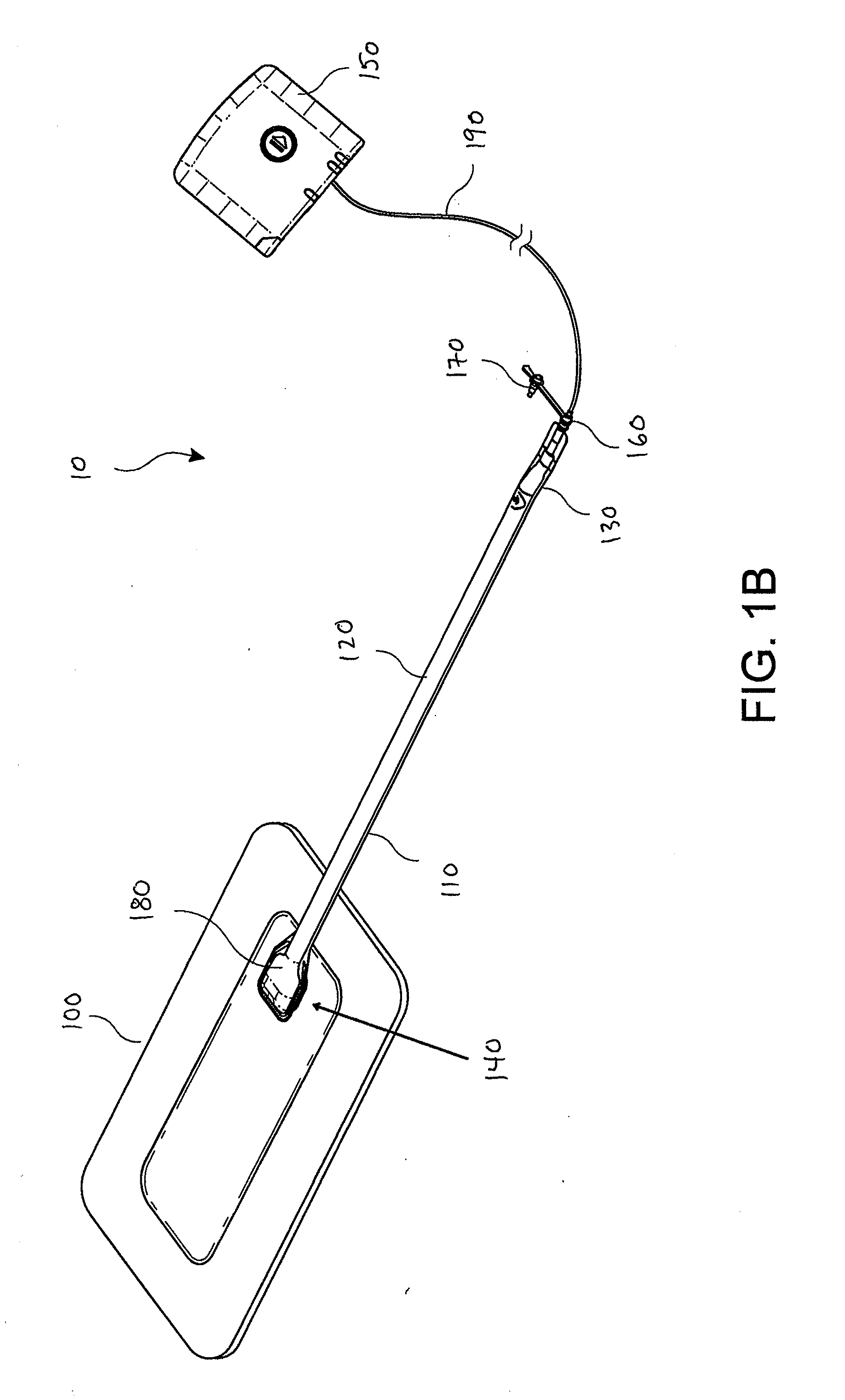
[0069]Preferred embodiments disclosed herein relate to wound therapy for a human or animal body. Therefore, any reference to a wound herein can refer to a wound on a human or animal body, and any reference to a body herein can refer to a human or animal body. The term “wound” as used herein, in addition to having its broad ordinary meaning, includes any body part of a patient that may be treated using negative pressure. Wounds include, but are not limited to, open wounds, incisions, lacerations, abrasions, contusions, burns, diabetic ulcers, pressure ulcers, stoma, surgical wounds, trauma and venous ulcers or the like. Treatment of such wounds can be performed using negative pressure wound therapy, wherein a reduced or negative pressure can be applied to the wound to facilitate and promote healing of the wound. It will also be appreciated that the fluidic connector and methods as disclosed herein may be applied to other parts of the body, and are not necessarily limited to treatment...


PUM


Abstract

Disclosed herein are several embodiments of a wound treatment apparatus employing a fluidic connector for negative pressure wound therapy and methods of using the same. Some embodiments are directed to improved fluidic connectors for connecting to a wound site, for example a fluidic connector including a reinforcement, and methods of using the same.

Description

BACKGROUND OF THE INVENTION[0001]1. Field of the Invention[0002]Embodiments of the present invention relate generally to the treatment of wounds using negative pressure wound therapy and more specifically to wound treatment apparatuses including a fluidic connector for use therewith.[0003]2. Description of the Related Art[0004]The treatment of open or chronic wounds that are too large to spontaneously close or otherwise fail to heal by means of applying negative pressure to the site of the wound is well known in the art. Negative pressure wound therapy (NPWT) systems currently known in the art commonly involve placing a cover that is impermeable or semi-permeable to fluids over the wound, using various means to seal the cover to the tissue of the patient surrounding the wound, and connecting a source of negative pressure (such as a vacuum pump) to the cover in a manner so that negative pressure is created and maintained under the cover. It is believed that such negative pressures pr...

Claims


Application Information

Patent Timeline
IPC IPC(8): A61M1/00A61F13/02
CPCA61M1/0086A61F13/0216A61M2205/7536A61M2205/7518A61F13/0206A61F13/00068A61M1/784A61M1/962A61M1/913A61M1/915A61M1/912A61M1/916A61M1/985
Inventor COLLINSON, SARAH JENNYGOWANS, JOHNGOWANS, PHILIP
Owner SMITH & NEPHEW INC
Why Eureka
Try Eureka