Optical semiconductor lighting apparatus

Inactive Publication Date: 2016-11-24
POSCO LED
View PDF7 Cites 9 Cited by
  • Summary
  • Abstract
  • Description
  • Claims
  • Application Information

AI Technical Summary

Benefits of technology

[0009]Exemplary embodiments provide an optical semiconductor lighting apparatus that is easy to asse

Problems solved by technology

Recently, the demand for lighting apparatuses using an optical semiconductor is increasing rapidly because such apparatuses have a long life span and are operable with a minimal amount of electric power.
However, the apparatuses need additional protection from severe condi

Method used


Image

  • Optical semiconductor lighting apparatus
  • Optical semiconductor lighting apparatus
  • Optical semiconductor lighting apparatus

Examples


Embodiment Construction

[0049]In the following description, for the purposes of explanation, numerous specific details are set forth in order to provide a thorough understanding of various exemplary embodiments. It is apparent, however, that various exemplary embodiments may be practiced without these specific details or with one or more equivalent arrangements. In other instances, well-known structures and devices are shown in block diagram form in order to avoid unnecessarily obscuring various exemplary embodiments.

[0050]In the accompanying figures, the size and relative sizes of layers, films, panels, regions, etc., may be exaggerated for clarity and descriptive purposes. Also, like reference numerals denote like elements.

[0051]When an element or layer is referred to as being “on,”“connected to,” or “coupled to” another element or layer, it may be directly on, connected to, or coupled to the other element or layer or intervening elements or layers may be present. When, however, an element or layer is re...


PUM


Abstract

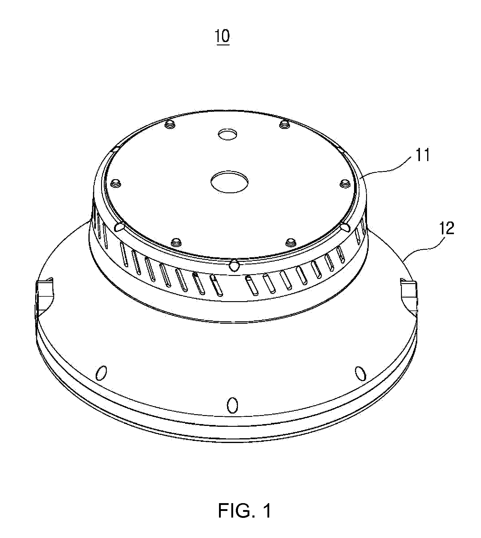
An optical semiconductor lighting apparatus including an upper part including a cover and a cooling member coupled to a lower surface of the cover and a lower part including a housing forming an inner space, a heat radiation member coupled to a lower side of the housing, and a light emitting member coupled to a lower surface of the heat radiation member. The upper part is mounted on top of the lower part and the cooling member is disposed over the heat radiation member at a predetermined distance.

Description

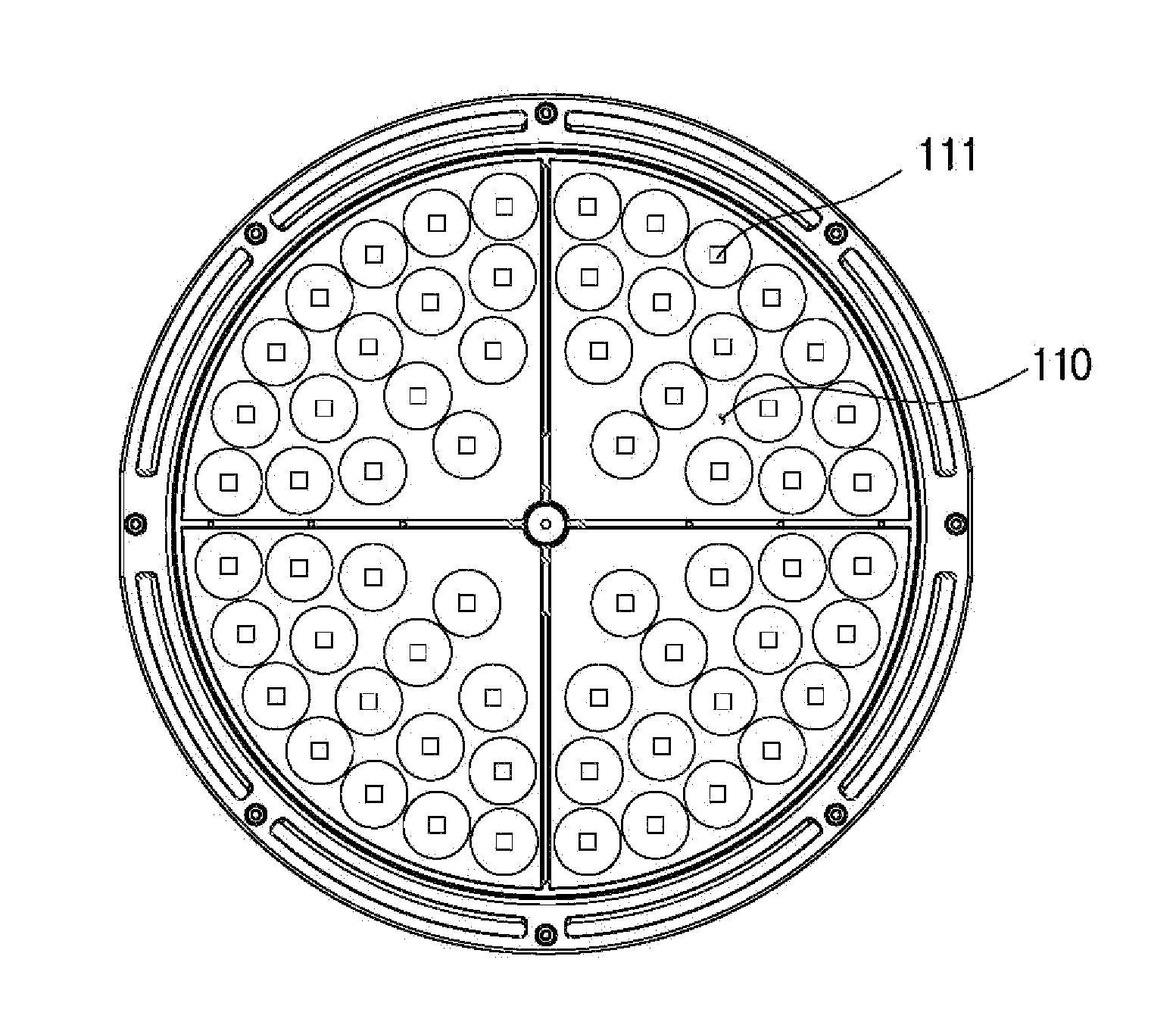
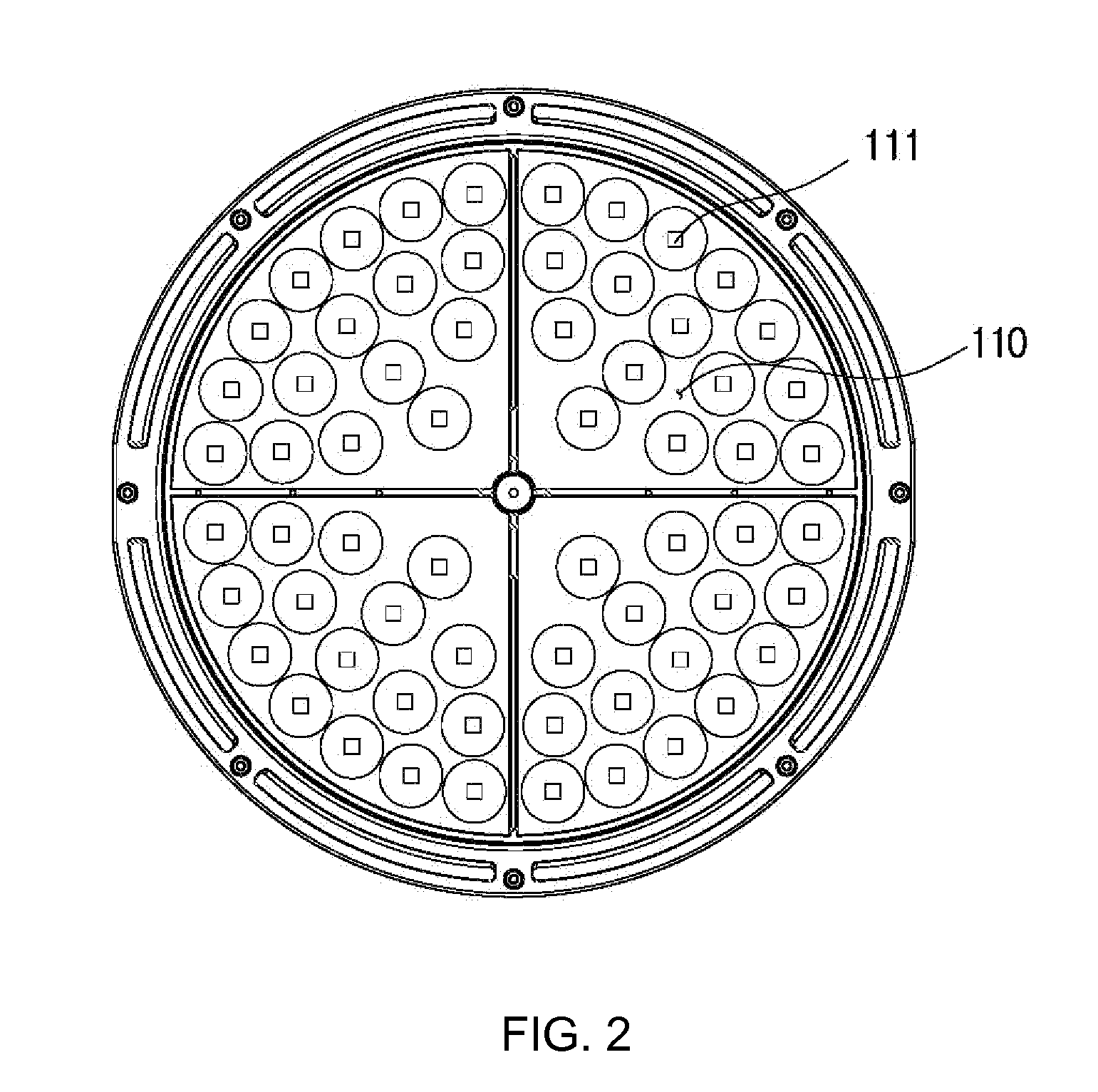
BACKGROUND[0001]1. Field[0002]Exemplary embodiments relate to an optical semiconductor lighting apparatus. More particularly, exemplary embodiments relate to an optical semiconductor lighting apparatus that is lightweight, small in size, and easily assembled. In addition, the optical semiconductor lighting apparatus provides adequate space for heat radiation with an air inlet and outlet. Furthermore, exemplary embodiments relate to an optical semiconductor lighting apparatus that is able to prevent dust and other harmful materials from sticking to it.[0003]2. Discussion of the Background[0004]Recently, the demand for lighting apparatuses using an optical semiconductor is increasing rapidly because such apparatuses have a long life span and are operable with a minimal amount of electric power. Furthermore, unlike some conventional lighting apparatuses, optical semiconductor lighting apparatuses are more environmentally friendly because they do not use toxic substances (e.g., mercury)...

Claims


Application Information

Patent Timeline
IPC IPC(8): F21V15/01F21V29/74F21V29/67
CPCF21V15/01F21V29/74F21V29/67F21S8/04F21W2131/40F21V29/773F21Y2105/10F21Y2115/10
Inventor LEE, SU WOONKIM, SANG HYUKJANG, YOON GILKIM, JUNG HWA
Owner POSCO LED
Why Eureka
Try Eureka