
Electrical cable with shielded conductors

Active Publication Date: 2016-11-24
TYCO ELECTRONICS LOGISTICS AG (CH)
View PDF3 Cites 17 Cited by
  • Summary
  • Abstract
  • Description
  • Claims
  • Application Information

AI Technical Summary

Benefits of technology

This patent is about an electrical cable design that includes a bundle of conductor assemblies. Each assembly has an inner conductor, insulator, and shield layer. The shield layer is made of a conductive plastic material to provide electrical shielding and flexibility. The shield layers of the two conductor assemblies are connected to each other to create a common electrical connection. Overall, this design provides better protection and flexibility for the cable.

Problems solved by technology

For example, helically wrapping the foil layer and the tape layer over the foil layer results in discontinuities that affect the signal integrity.
Increasing the overlay may improve insertion loss by pushing the attenuation outside of an operational range of bandwidths, although it may also undesirably increase the rigidity or stiffness of the cable, as well as increase manufacturing time and material usage.
Thus, there is a trade-off between signal integrity, flexibility, and manufacturing costs.

Method used


Image

  • Electrical cable with shielded conductors
  • Electrical cable with shielded conductors
  • Electrical cable with shielded conductors

Examples


Embodiment Construction

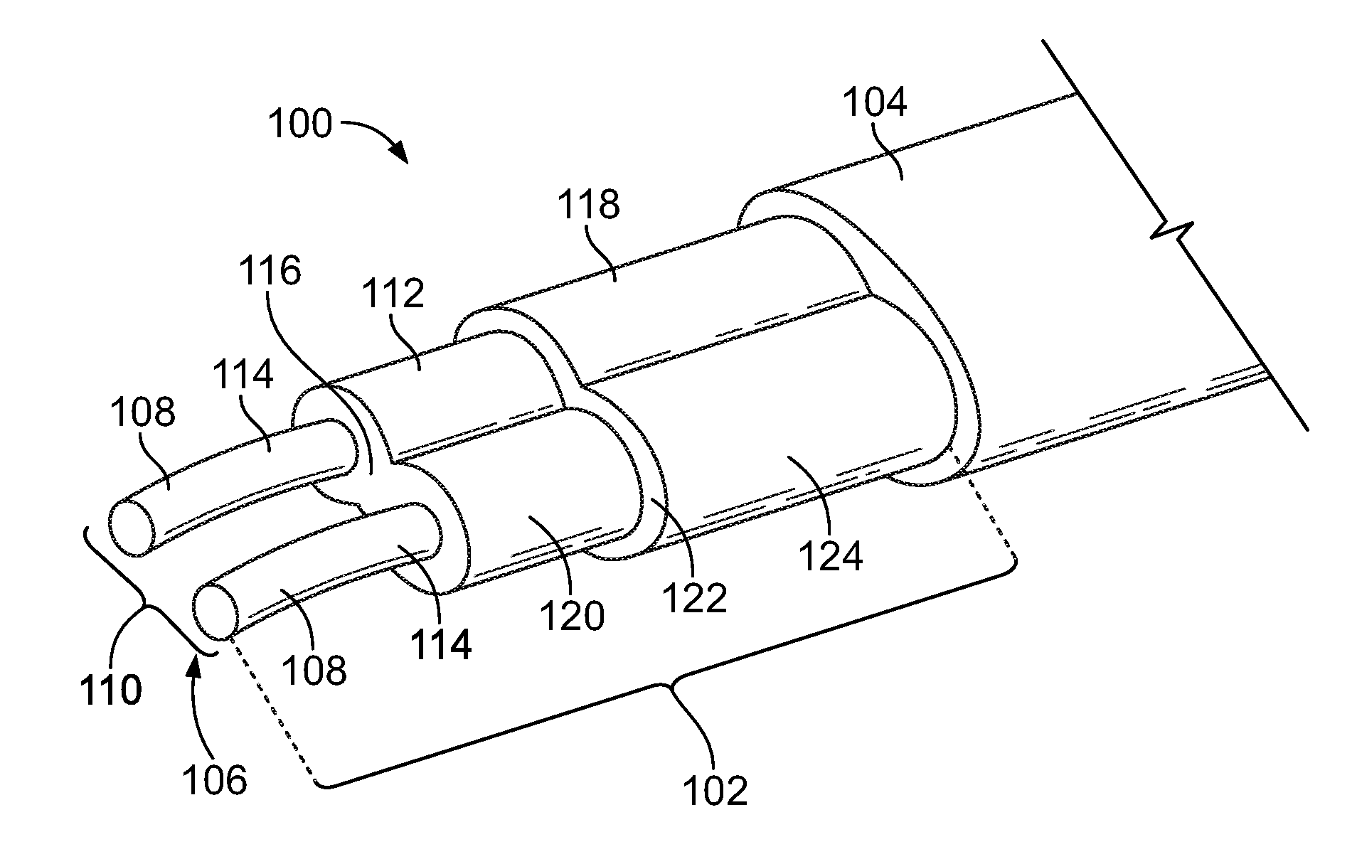
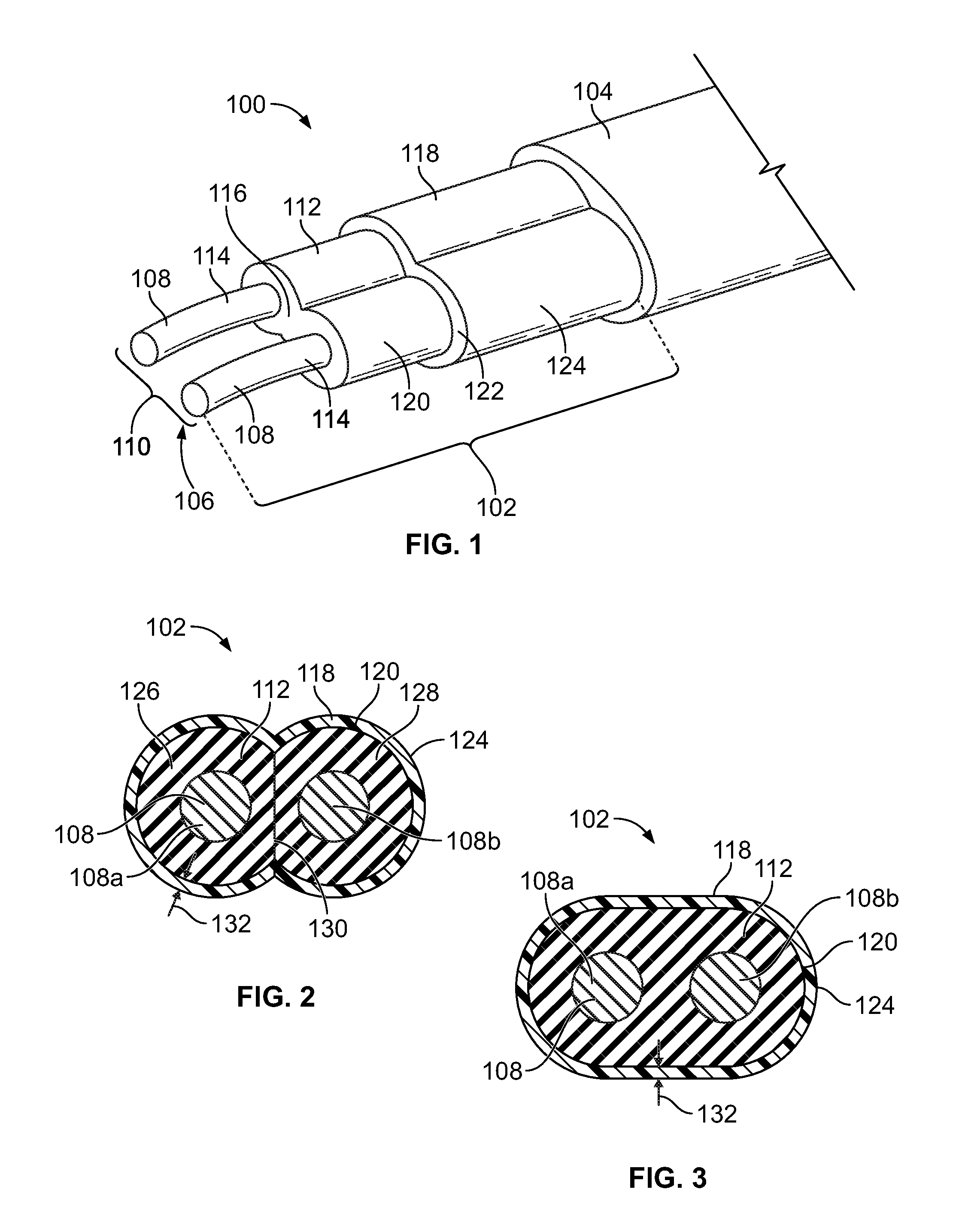
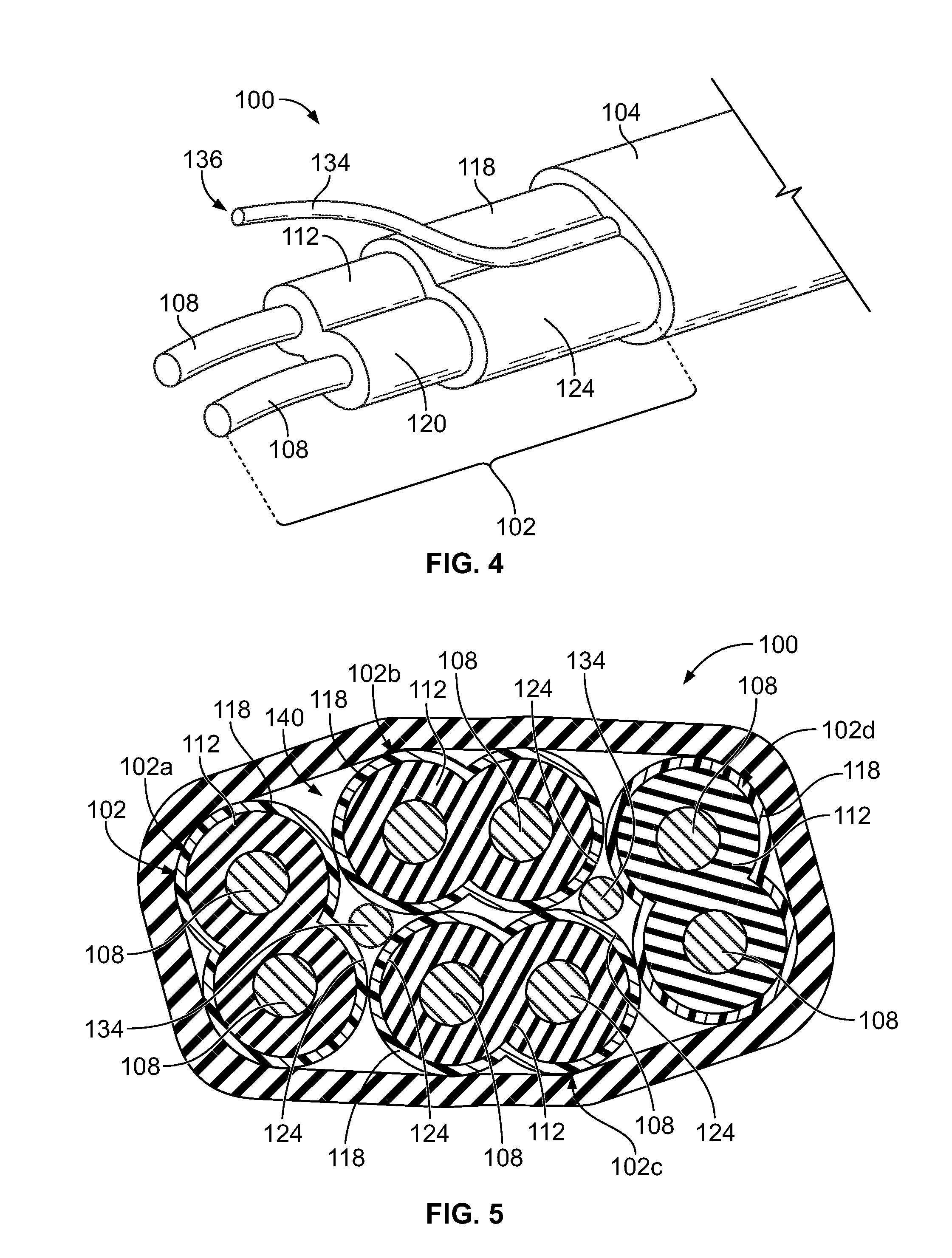
[0013]FIG. 1 is a perspective view of a portion of an electrical cable 100 formed in accordance with an embodiment. The electrical cable 100 may be used for high speed data transmission between two electrical devices, such as electrical switches, routers, and / or host bus adapters. For example, the electrical cable 100 may be configured to transmit data signals at speeds of at least 10 gigabits per second (Gbps), which is required by the enhanced small form-factor pluggable (SFP+) standard. For example, the electrical cable 100 may be used to provide a signal path between high speed connectors that transmit data signals at speeds between 10 and 30 Gbps, or more. It is appreciated, however, that the benefits and advantages of the subject matter described and / or illustrated herein may accrue equally to other data transmission rates and across a variety of systems and standards. In other words, the subject matter described and / or illustrated herein is not limited to data transmission ra...


PUM


Abstract

An electrical cable includes at least one conductor assembly. Each conductor assembly includes at least one inner conductor that extends along a length, an insulator, and a shield layer. The insulator engages and surrounds a surface of the at least one inner conductor. The insulator is composed of a dielectric material. The shield layer engages and surrounds an outer perimeter of the insulator. The shield layer is formed of a conductive plastic material to provide electrical shielding for the at least one inner conductor and flexibility.

Description

BACKGROUND OF THE INVENTION[0001]The subject matter herein relates generally to electrical cables that provide shielding around signal conductors.[0002]Shielded electrical cables are used in high-speed data transmission applications in which electromagnetic interference (EMI) and / or radio frequency interference (RFI) are concerns. Electrical signals routed through shielded cables may radiate less EMI / RFI emissions to the external environment than electrical signals routed through non-shielded cables. In addition, the electrical signals being transmitted through the shielded cables may be better protected against interference from environmental sources of EMI / RFI than signals through non-shielded cables.[0003]Shielded electrical cables are typically provided with a shield layer formed by a metal foil. Signal conductors are typically surrounded by an insulation layer, and the metal foil is subsequently wrapped around the insulation layer to provide shielding for the signal conductors ...

Claims


Application Information

Patent Timeline
IPC IPC(8): H01B11/18H05K9/00H01B1/22H01B7/02H01B11/00
CPCH01B11/1895H01B7/0216H01B11/002H05K9/0098H01B1/22H01B11/1891H01B11/1878H01B11/20
Inventor NICHOLS, ROBERT PAUL
Owner TYCO ELECTRONICS LOGISTICS AG (CH)
Learn More