Image data generator and three-dimensional printing apparatus including the same

Inactive Publication Date: 2016-12-01
ROLAND DG CORP
View PDF3 Cites 6 Cited by
  • Summary
  • Abstract
  • Description
  • Claims
  • Application Information

AI Technical Summary

Benefits of technology

[0012]The image data generator according to this preferred embodiment colors the first boundary area and the second boundary area, which are included in a boundary region straddling the boundary between the first and second surfaces, in the above-described manner. This visually blurs the boundary region in the image data of the three-dimensional object. Consequently, the image data generator according to this preferred embodiment reduces visual di

Problems solved by technology

In this case, however, coloring the three-dimensional object in accordance with image data makes it difficult to color a boundary region straddling the boundary between the first and second surfaces (i.e., a region including an area of the first surface close to the boundary and an area of the second surface close to the boundary) such that the first and second surfaces are respectively distinctly colored with the first an

Method used


Image

  • Image data generator and three-dimensional printing apparatus including the same
  • Image data generator and three-dimensional printing apparatus including the same
  • Image data generator and three-dimensional printing apparatus including the same

Examples


Embodiment Construction

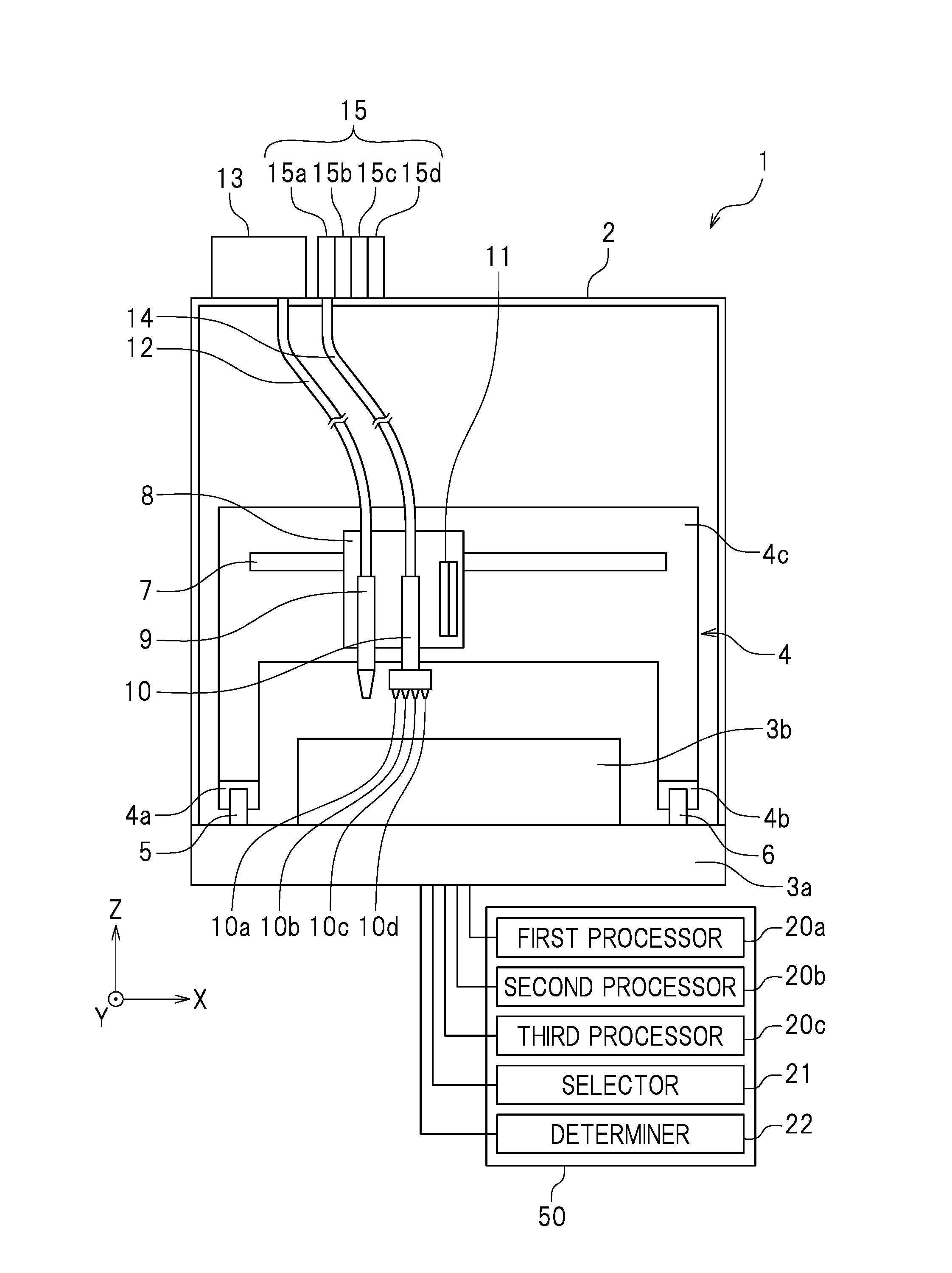
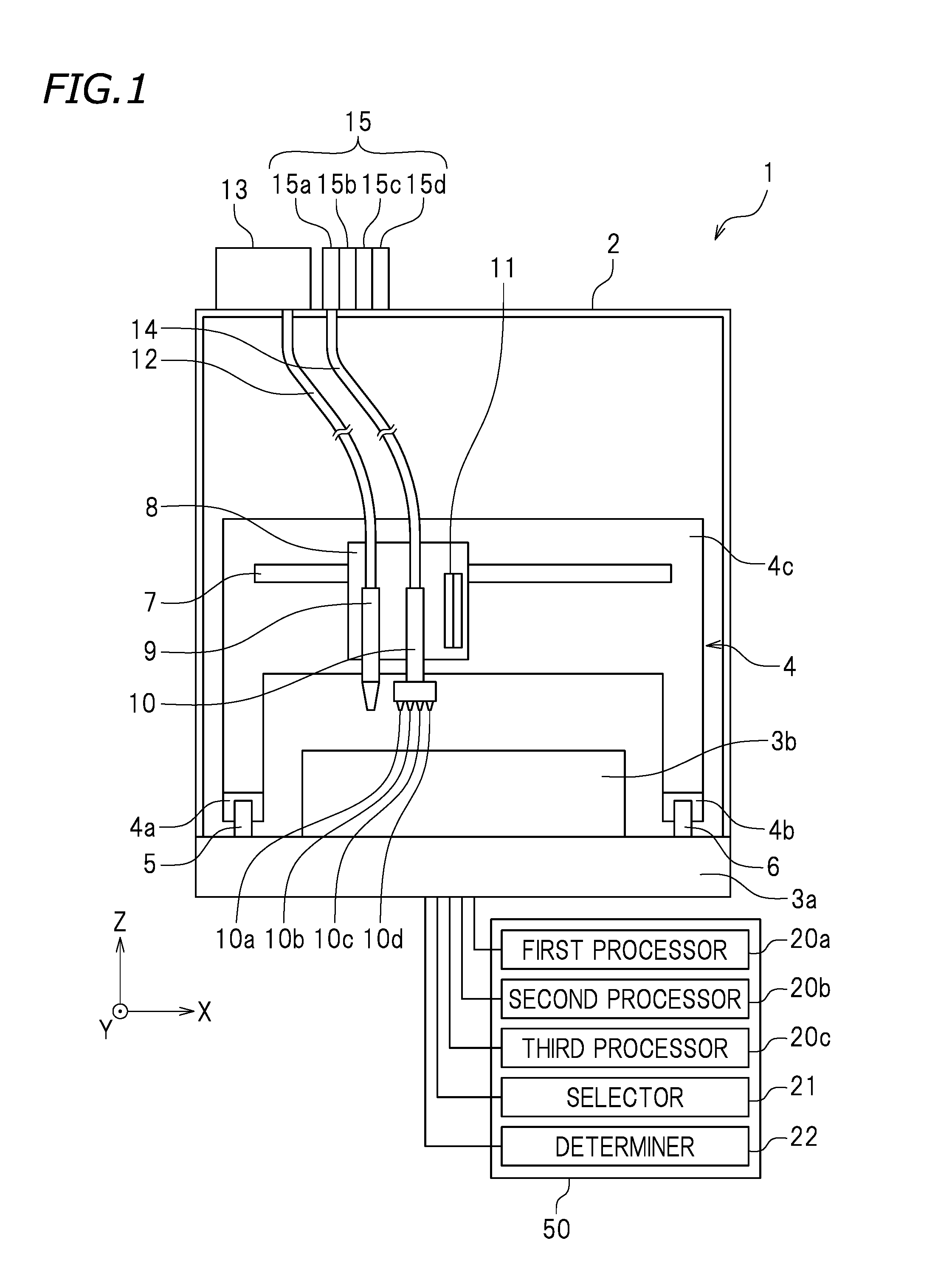
[0020]Preferred embodiments of the present invention will be described below with reference to the drawings. As illustrated in FIG. 1, axes perpendicular to each other are defined as an “X axis”, a “Y axis”, and a “Z axis”. A three-dimensional printing apparatus 1 is placed on a plane defined by the X and Y axes. As used herein, the terms “rightward” and “leftward” respectively refer to the direction toward the right of FIG. 1 and the direction toward the left of FIG. 1. As used herein, the terms “forward” and “rearward” respectively refer to the direction toward the viewer of FIG. 1 and the direction away from the viewer of FIG. 1. Note that these directions are defined merely for the sake of convenience and are not intended to limit in any way how the three-dimensional printing apparatus 1 may be installed.

[0021]As illustrated in FIG. 1, the three-dimensional printing apparatus 1 preferably has a box shape. Specifically, the three-dimensional printing apparatus 1 preferably includ...


PUM

PropertyMeasurementUnit
Angleaaaaaaaaaa
Angleaaaaaaaaaa
Coloraaaaaaaaaa

Abstract

An image data generator includes a first coloring processor that colors each of portions of a first surface area and each of portions of a second surface area with a first color and a second color, respectively, a second coloring processor that colors some of portions of a first boundary area with the first color and color the other portions with the second color, or colors one or more of the portions of the first boundary area with a mixed color that is a mixture of the first and second colors, and a third coloring processor that colors some of portions of a second boundary area with the second color and color the other portions with the first color, or colors one or more of the portions of the second boundary area with the mixed color that is a mixture of the first and second colors.

Description

CROSS-REFERENCE TO RELATED APPLICATIONS[0001]This application claims priority to Patent Application No. 2015-109687 filed in Japan on May 29, 2015, the entire contents of which are hereby incorporated by reference.BACKGROUND OF THE INVENTION[0002]1. Field of the Invention[0003]The present invention generally relates to image data generators and three-dimensional printing apparatuses, and more particularly relates to an image data generator that generates image data of a three-dimensional object and a three-dimensional printing apparatus including the image data generator.[0004]2. Description of the Related Art[0005]A three-dimensional printing apparatus known in the art sequentially stacks layers each having a predetermined cross-sectional shape, thus printing a three-dimensional object.[0006]Printing methods performed by three-dimensional printing apparatuses include inkjet printing, fused deposition modeling, stereolithography, plaster-based 3D printing, and selective laser sinter...

Claims


Application Information

Patent Timeline
IPC IPC(8): B29C67/00
CPCB29C67/0088B29C67/0085B29K2995/0021B33Y30/00B33Y50/02B29C67/0059B29C64/112B29C64/209B29C64/386
Inventor KOBAYASHI, KOUICHI
Owner ROLAND DG CORP
Why Eureka
Try Eureka