Lifting hoist with hysteresis clutch

a clutch and hoist technology, applied in the field of hoists, can solve the problems of torque limit, torque vibration in the drive train, no additional clutch element provided or active, etc., and achieve the effect of more problem-free operation

Active Publication Date: 2016-12-01
KONECRANES GLOBAL
View PDF1 Cites 6 Cited by
  • Summary
  • Abstract
  • Description
  • Claims
  • Application Information

AI Technical Summary

Benefits of technology

The technical effect of this patent is to improve the performance of hoists used for lifting heavy objects by reducing operational issues.

Problems solved by technology

The technical problem addressed in this patent relates to developing effective mechanisms to prevent overload and damage to hoists caused by various operative scenarios including but not limited to: (a) loading errors; (b) unexpected resistance from objects/obstacles; (c) excessive strain on parts resulting from sudden changes in rotation speed or acceleration/deceleration rates during operation switchings or pole change events; and (d) potential risks associated with inverter-controlled drives. These solutions should ensure safe and reliable performance of hoists without compromizing their efficiency and affordability.

Method used


Image

  • Lifting hoist with hysteresis clutch
  • Lifting hoist with hysteresis clutch
  • Lifting hoist with hysteresis clutch

Examples


Embodiment Construction

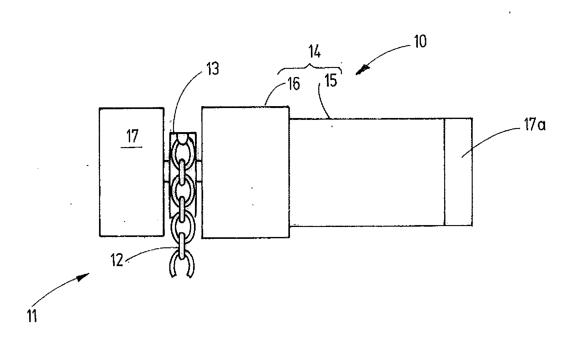
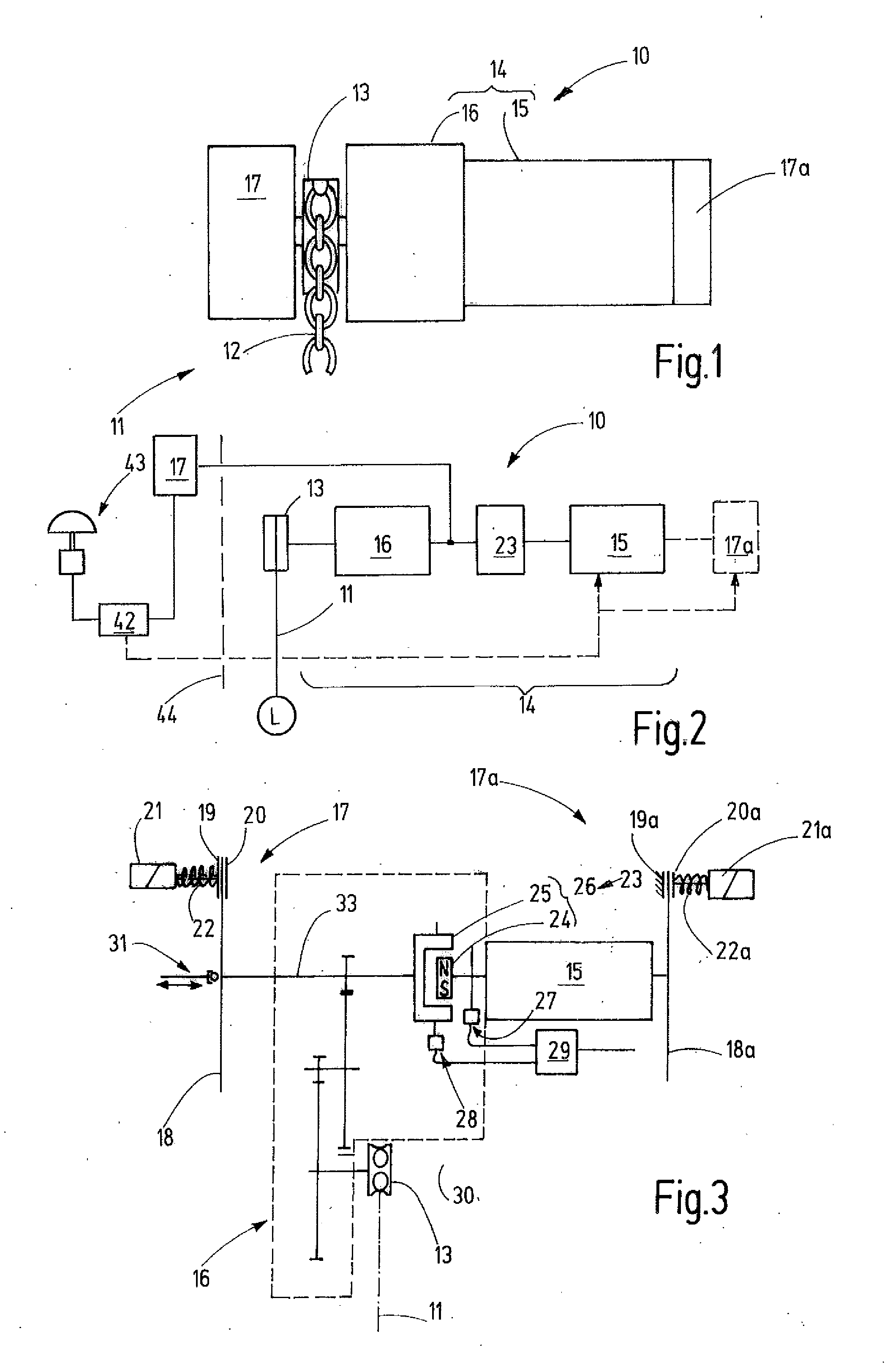
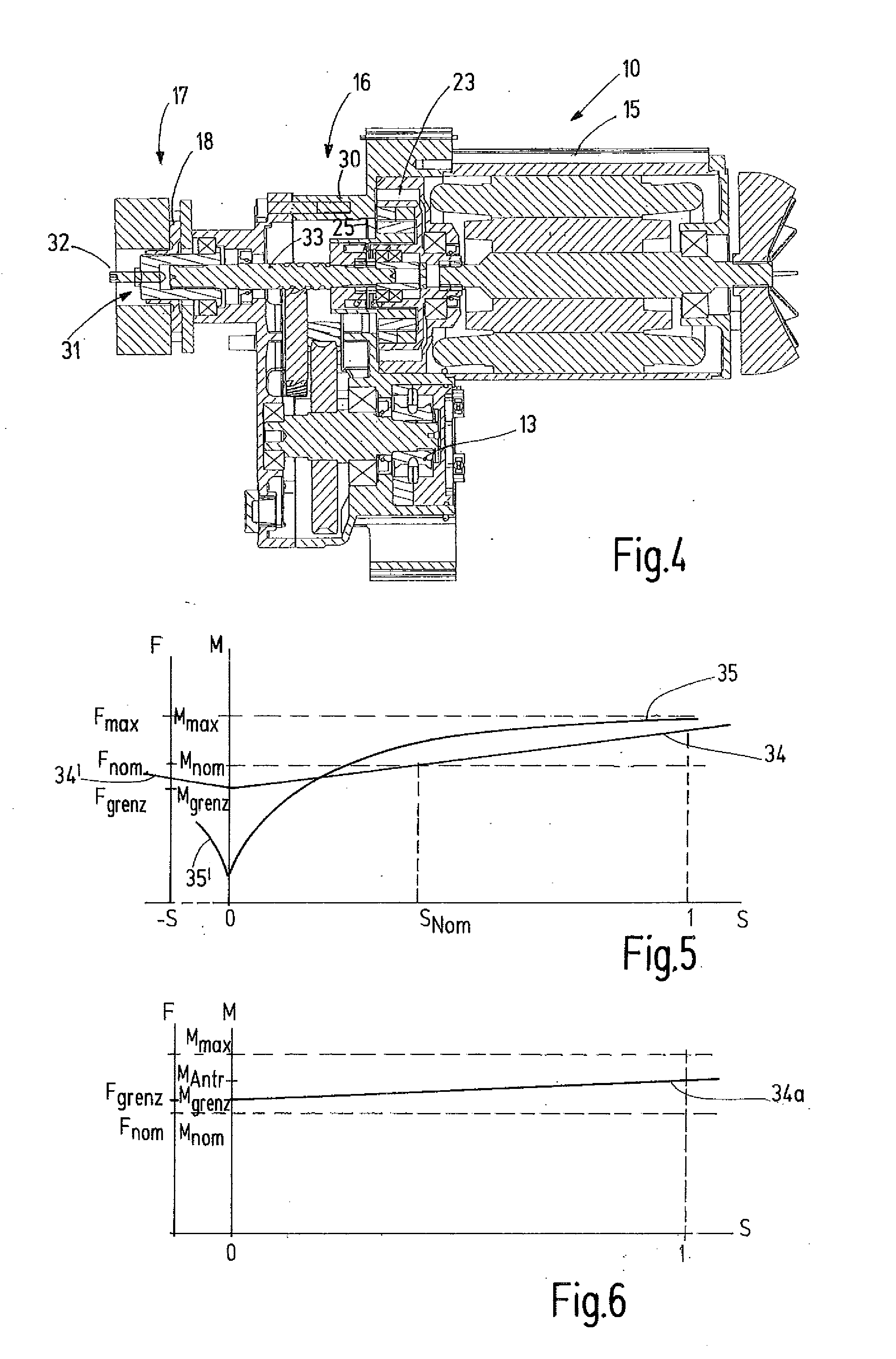
[0031]Referring more particularly to the drawings, there is shown an illustrative hoist 10 in accordance with the invention which may be part of a crane, a crane system or the like. The hoist 10 is disposed for lifting loads L (FIG. 2) by means of a pulling means or element 11 configured, for example, as a round-link chain 12, another chain, a rope or the like, or for moving such loads in another way. To do so, the chain 12 moves over a pocket wheel 13 that is connected to the output side of a drive train 14. The drive train 14 comprises a motor 15, preferably an electromotor, as well as, preferably, a gearing 16. The motor 15 may be an asynchronous motor, a synchronous motor or another electromotor, a hydraulic motor, compressed air motor or another driving source. In the simplest case, it may be a mains-operated motor that can be switched on and off and has a single fixed rotational speed (for example 1500 rpm or 3000 rpm). Alternatively, as a mains-operated motor, the motor 15 ma...


PUM


Abstract

A lifting hoist (10) having a drive train (14) containing a slip clutch arrangement (23) with a hysteresis clutch (26). The drive train (14) transfers torque, friction-free, in both forward and backward directions of movement between the motor (15) and a gearing (16). The hysteresis clutch (23) forms an unbranched torque transmission path between the motor (15) and the gearing (16). The hysteresis clutch (26) acts as a vibration damper, allows controlled emergency load lowering, and acts as a secure torque limiter in emergency malfunctions when lowering a load. It further can be used as a load indicator by reducing the load-lifting speed before the nominal load is reached or in the event of an overload.

Description


Claims


Application Information

Patent Timeline
Owner KONECRANES GLOBAL
Why Eureka
Try Eureka