
Autostereoscopic System

Active Publication Date: 2016-12-01
SEEFRONT
View PDF9 Cites 2 Cited by
  • Summary
  • Abstract
  • Description
  • Claims
  • Application Information

AI Technical Summary

Benefits of technology

The invention improves the optical quality of autostereoscopic displays by providing a refraction-corrected channel mask that is more accurate for large skew angles. This allows for high image quality even for larger screen dimensions, and makes it easier to adapt the system to different types of parallax filter devices and displays with curved screens.

Problems solved by technology

Conventional systems for presenting different images to the left and right eyes of the user employ headsets or shutter glasses which, however, are quite disturbing for the user.

Method used


Image

  • Autostereoscopic System
  • Autostereoscopic System
  • Autostereoscopic System

Examples


Embodiment Construction

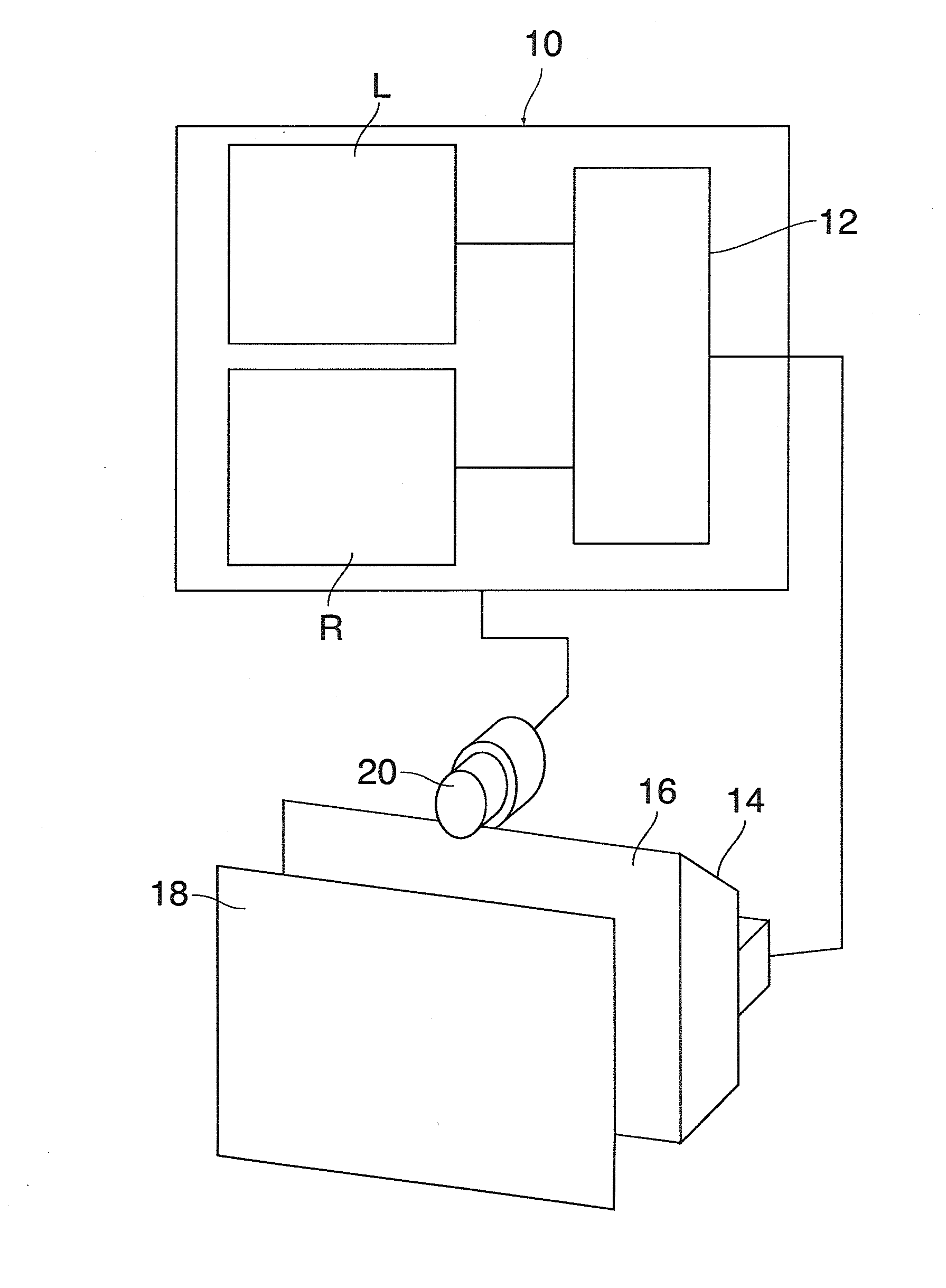
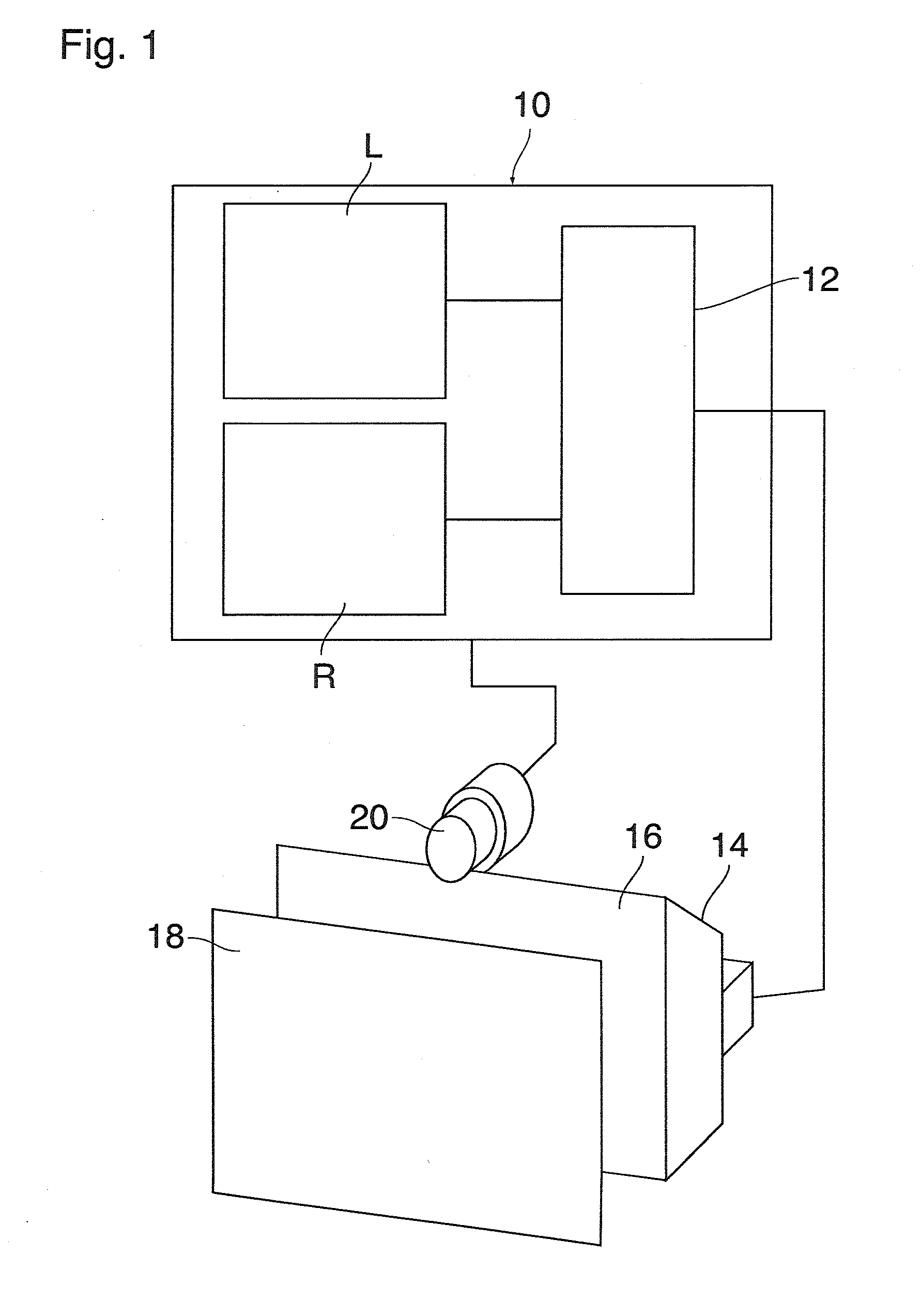
[0026]The system shown in FIG. 1 comprises a computer system 10, e.g. a personal computer, including a graphics card 12 which drives a display 14 so as to display images on a screen 16 of the display. A parallax filter device, e.g. a lens array 18 is disposed in front of the screen 16, and a video camera forming part of an eye tracking or head tracking system 20 is attached to the display 14 and communicates with the computer system 10.

[0027]The graphics card 12 has access to two texture maps L and R that are stored in a memory of the computer system 10. The texture map L stores image information of a left channel, i.e. image information that is to be displayed to the left eye of a user (not shown) who looks at the screen 16 through the lens array 18. Similarly, the texture map R stores image information of the right channel for the right eye of the user. The head tracking system 20 keeps track of any movements of the head of the user and signals these movements to the computer syst...


PUM


Abstract

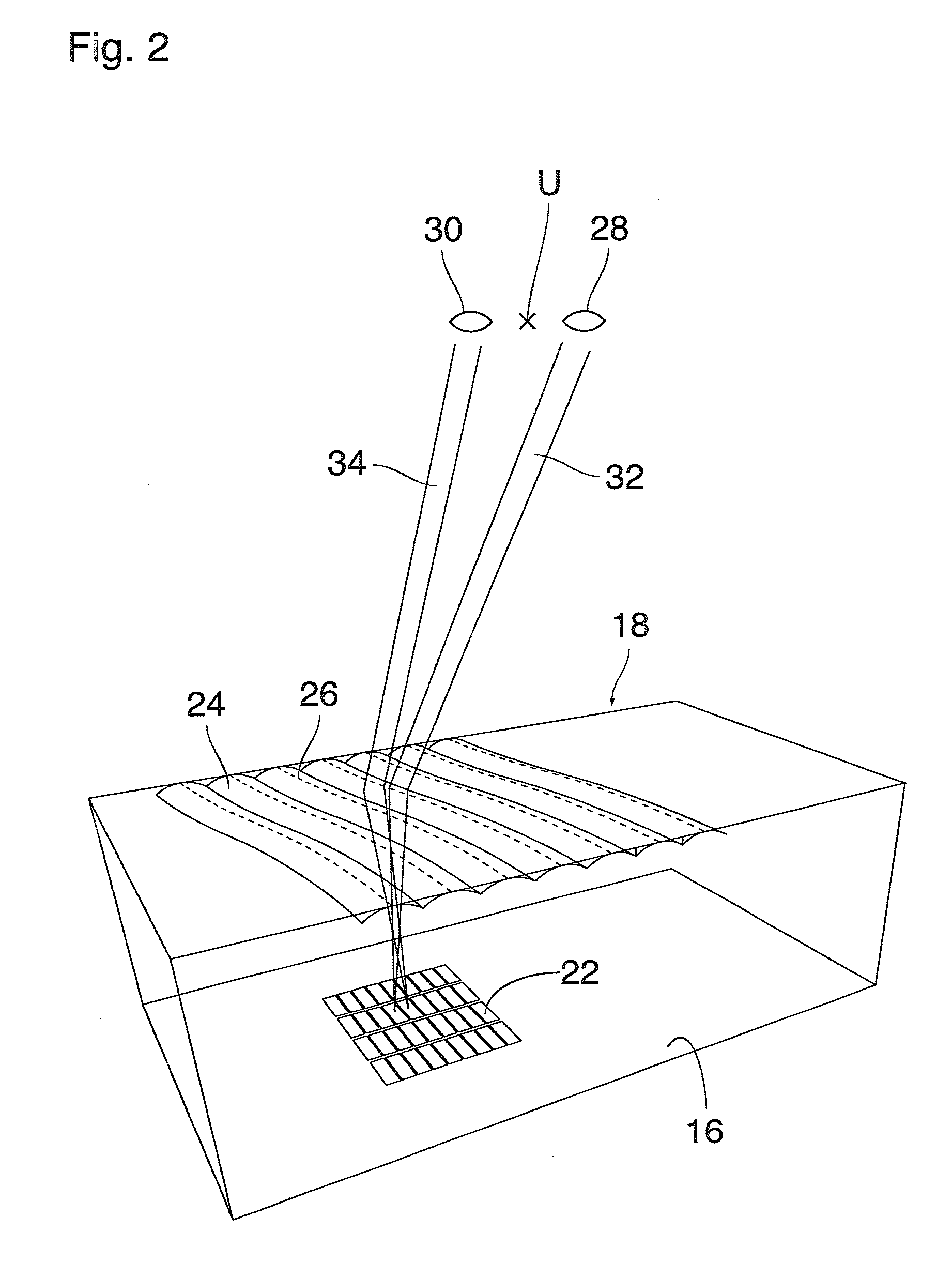
A method of constructing a channel mask for an autostereoscopic display, the display including an electronically controlled screen covered by a parallax filter device that includes a refractive medium and is configured to obscure certain areas on the screen for a left eye of a viewer and to obscure certain other areas on the screen for a right eye of the viewer, the channel mask being a two-dimensional geometric object that permits to assign to each point on the screen one of a number of viewing positions of an eye of the viewer, the method including the step of constructing the channel mask by tracing light rays that propagate from selected points on the screen and are refracted at the parallax filter device.

Description

BACKGROUND OF THE INVENTION[0001]The invention relates to a method of constructing a channel mask for an autostereoscopic display, the display comprising an electronically controlled screen covered by a parallax filter device that includes a refractive medium and is configured to obscure certain areas on the screen for a left eye of a viewer and to obscure certain other areas on the screen for a right eye of the viewer, the channel mask being a two-dimensional geometric object that permits to assign one of a number of pre-defined viewing positions of an eye of the viewer to each point on the screen.[0002]According to the general principles of stereoscopy, an impression of spatial depth is generated by presenting to the two eyes of a viewer two different images that show the same scene from slightly different perspectives which represent the parallax difference between the left right and eye of the viewer.[0003]Conventional systems for presenting different images to the left and righ...

Claims


Application Information

Patent Timeline
IPC IPC(8): G02B27/00H04N13/04G02B27/22G02B30/27
CPCG02B27/0012G02B27/2214H04N13/0497H04N13/0484H04N13/0468H04N13/0409G02B27/0093G02B30/27H04N13/302H04N13/31H04N13/359H04N13/366H04N13/38H04N13/383H04N13/398
Inventor GROSSMANN, CHRISTOPH
Owner SEEFRONT
Learn More