
Thin glass substrate, method and apparatus for its production

Pending Publication Date: 2019-10-10
SCHOTT AG
View PDF0 Cites 1 Cited by
  • Summary
  • Abstract
  • Description
  • Claims
  • Application Information

AI Technical Summary

Benefits of technology

The invention is about improving the quality of thin glass substrates used in optical devices like laminated glass panes and motor vehicle glazing. The invention involves adjusting the viscosity of the glass to ensure better optical quality. The use of thin glass substrates in these applications provides improved design flexibility and reduced weight. The optical quality of the glass can be determined using a simple method that measures the backward angle of light scattering.

Problems solved by technology

However, the reduction in microcorrugation has only a minor effect on the visual conspicuousness of drawing streaks.
Previous mathematical models suggested that higher processing temperatures would also provide higher optical quality, so, initially, the increased viscosity associated with a reduction in temperature did not appear to be a promising measure for achieving improved optical quality.
Furthermore, higher viscosities of the glass to be melted which are associated with low temperatures are rather unfavorable for melting tanks, since homogenization of the glass may become more difficult with increasing viscosity.
Furthermore, cooling of the glass to be hot formed normally precludes a high throughput, since the then more viscously flowing glass has the tendency to reduce the flow rate within the hot forming process chain.
For this reason, it has hitherto been considered to be particularly disadvantageous to intervene in the process chain of hot forming to reduce the temperature, in particular if this occurred at an early point in time and thus affected the entire process chain.
Elevations on one of the main surfaces of a thin glass substrate, in particular elongated elevations extending on the float glass in a main direction, the drawing or advancement direction of the glass to be hot formed, and which are commonly referred to as drawing streaks, can lead to a marked degradation of the optical properties if they exceed a particular size, and may even have the effect of a cylindrical lens in the respective optical beam path.
However, a drawback of these shadow casting procedures is that both faces of a glass substrate are captured in the transmission light operating mode that is normally employed, so that no information is obtained about the optical interaction of only one face.
If maximum deviation angles of an optical measuring beam are determined in a measurement in back reflection, this value is only of secondary importance as well, since in this case there will be insufficient information about the properties of a system formed with this measured main surface.

Method used


Image

  • Thin glass substrate, method and apparatus for its production
  • Thin glass substrate, method and apparatus for its production
  • Thin glass substrate, method and apparatus for its production

Examples


Embodiment Construction

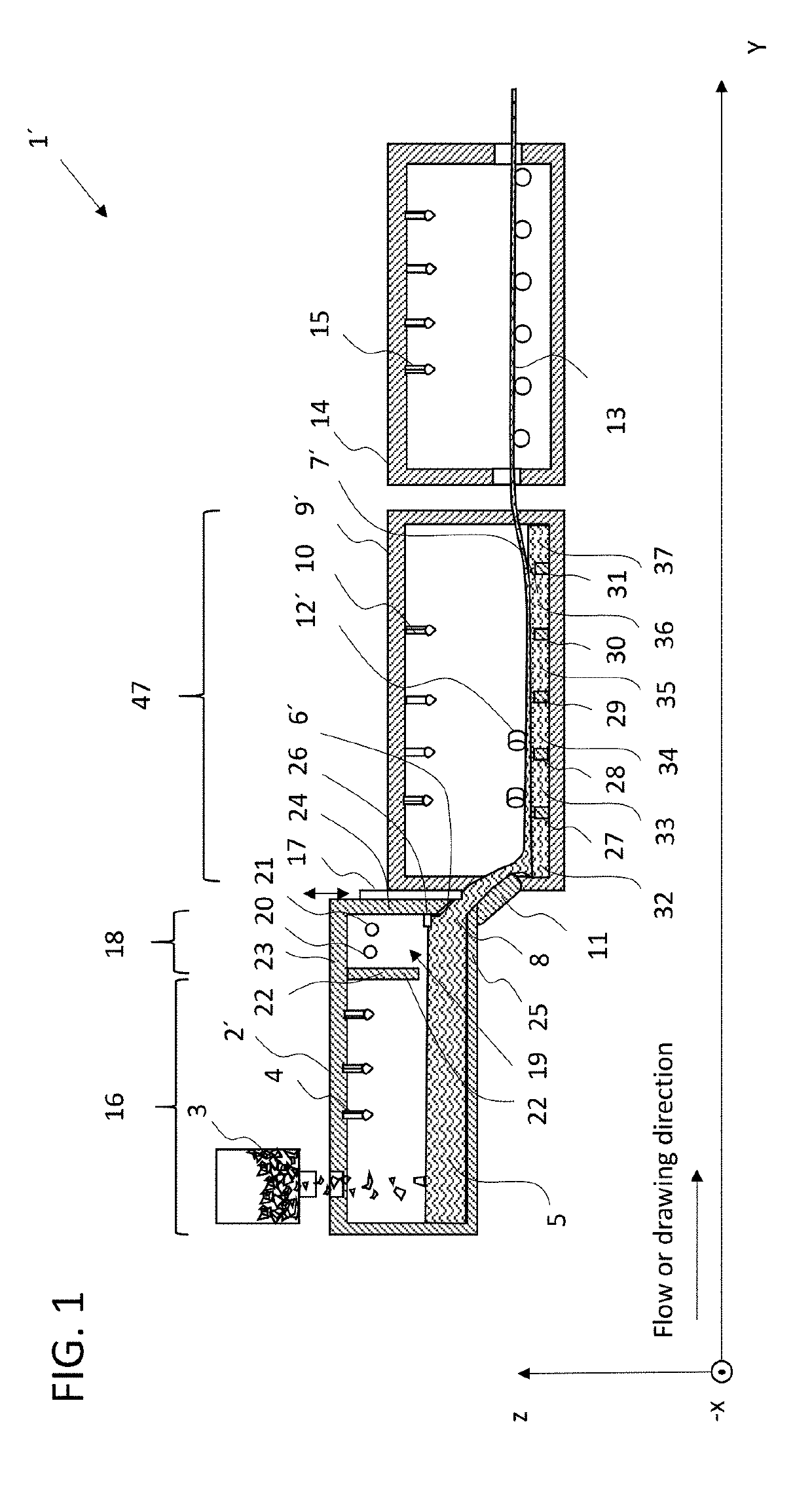
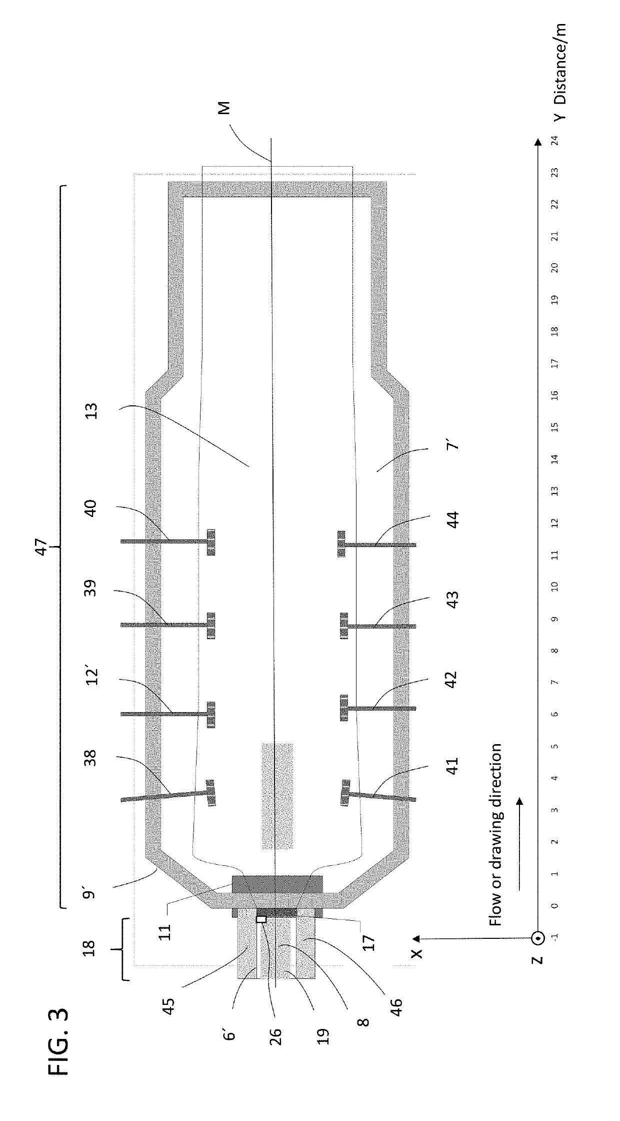
[0084]In the following description of preferred and particularly preferred embodiments, the same reference numerals in the various figures designate the same or equivalent components of the respective apparatus disclosed herein.

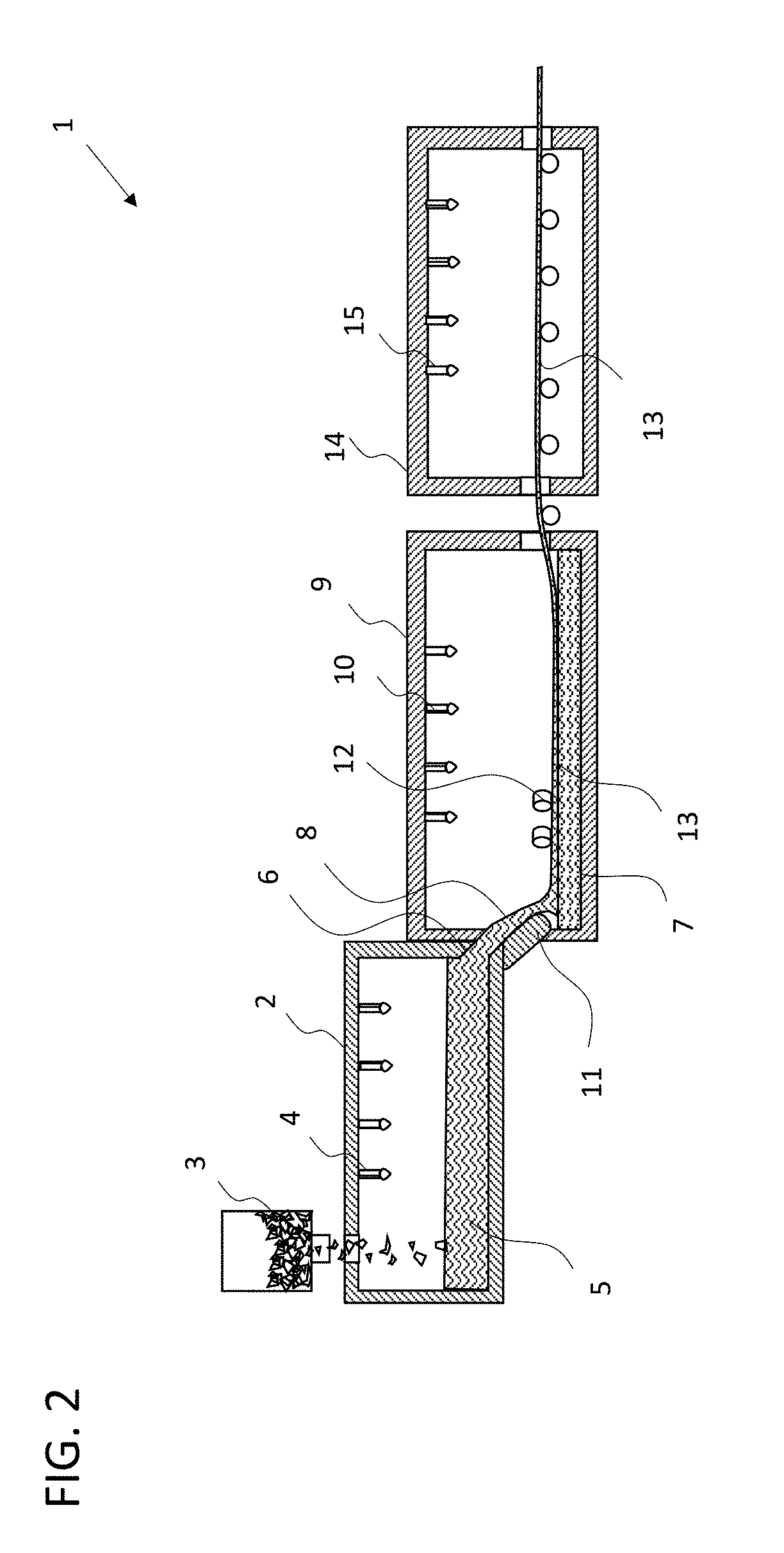
[0085]Referring first to the prior art system for producing float glass as shown in FIG. 2, which is overall designated by reference numeral 1, similar to the apparatus according to the invention.

[0086]This float system comprises a melting furnace 2, also referred to as a melting tank, to which a glass batch 3 to be melted is fed in known manner and is heated by burners 4 until a glass melt 5 of the desired composition is obtained. Further devices for homogenization of the molten glass will be known to a person skilled in the art and are therefore not described in more detail.

[0087]Through a channel 6, the molten glass of glass melt 5 reaches a float bath 7, usually under the influence of gravity, which float bath comprises liquid tin on which the glass 8 to ...


PUM

PropertyMeasurementUnit
Temperatureaaaaaaaaaa

Abstract

A thin glass substrate, as well as a method and an apparatus are provided. The glass substrate has a glass having first and second main surfaces and elongated elevations on one of the main surfaces. The elevations rise in a normal direction, have a longitudinal extent that is greater than two times a transverse extent, and have a height, on average, that is less than 100 nm, and with a transverse extent of the elevation smaller than 40 mm. The method includes melting a glass, hot forming the glass, and adjusting a viscosity of the glass so that for the viscosity θ1 for a first stretch over a first distance of up to 1.5 m downstream of a flow rate control component and y1 indicating a second distance to a location immediately downstream the flow rate control component the equation lg η1(y1) / dPa·s=(lg η01 / dPa·s+a1(y1)) applies.

Description

CROSS REFERENCE TO RELATED APPLICATIONS[0001]This application is a continuation of International Application No. PCT / EP2017 / 083554 filed Dec. 19, 2017, which claims benefit under 35 USC 119 of German Application No 10 2016 125 488.6 filed Dec. 22, 2016 and German Application No 10 2017 124 625.8 filed Oct. 20, 2017, the entire content of all of which are incorporated herein by reference.BACKGROUND1. Field of the Invention[0002]The invention relates to a thin glass substrate, to a method and to an apparatus for its production. Furthermore, measurement methods are specified for determining the optical quality, in particular of thin glass substrates produced according to the method.2. Description of Related Art[0003]Thin glass substrates are of increasing importance, inter alia in automotive engineering, since they not only allow to reduce the weight of a motor vehicle, but can also have a significant impact on the optical properties of the glazing thereof.[0004]With increasing demands...

Claims


Application Information

Patent Timeline
IPC IPC(8): C03B18/02B32B17/10B32B3/30C03C3/087
CPCC03C21/002B32B2605/006C03C3/087B32B17/10119B32B2315/08B32B3/30C03B18/02B32B17/10036C03B17/064B32B17/10137C03C3/093B32B17/10045B32B2329/04B32B2329/06B32B2551/00B32B2571/00C03C3/083C03B23/023B32B3/02B32B3/26B32B3/263Y10T428/24777
Inventor VOGL, ARMINSCHMIADY, THOMASZACHAU, THILOALKEMPER, JOCHENMEISTER, MICHAELKUNERT, CHRISTIANKLIPPE, LUTZDIETRICH, RÜDIGER
Owner SCHOTT AG
Learn More