Liquid crystal display panel and device thereof

Inactive Publication Date: 2016-12-01
SHENZHEN CHINA STAR OPTOELECTRONICS TECH CO LTD
View PDF7 Cites 7 Cited by
  • Summary
  • Abstract
  • Description
  • Claims
  • Application Information

AI Technical Summary

Benefits of technology

[0009]The objective of the present invention is to provide an LCD panel and an LCD device to solve the technical problems in

Problems solved by technology

However, the common voltage in an LCD panel which has the aforementioned structure is prone to coupling occurrence while the polarity

Method used


Image

  • Liquid crystal display panel and device thereof
  • Liquid crystal display panel and device thereof
  • Liquid crystal display panel and device thereof

Examples


Embodiment Construction

[0047]The preferred embodiments of the present invention will be detailed in the following in combination with the accompanying drawings. Spatially relative terms mentioned herein, such as “above”, “beneath”, “front”, “back”, “left”, “right”, “inner”, “outer”, “lateral”, and the like may be used to describe one element's relationship to another element(s) as illustrated in the figures. Furthermore, the articles “a” and “an” as used in this specification and the appended claims should generally be construed to mean “one or multiple”, unless specified or clear from context to be directed to be a singular form. The drawings are drawn schematically and the same reference numbers are used to indicate the same or similar components throughout the drawings.

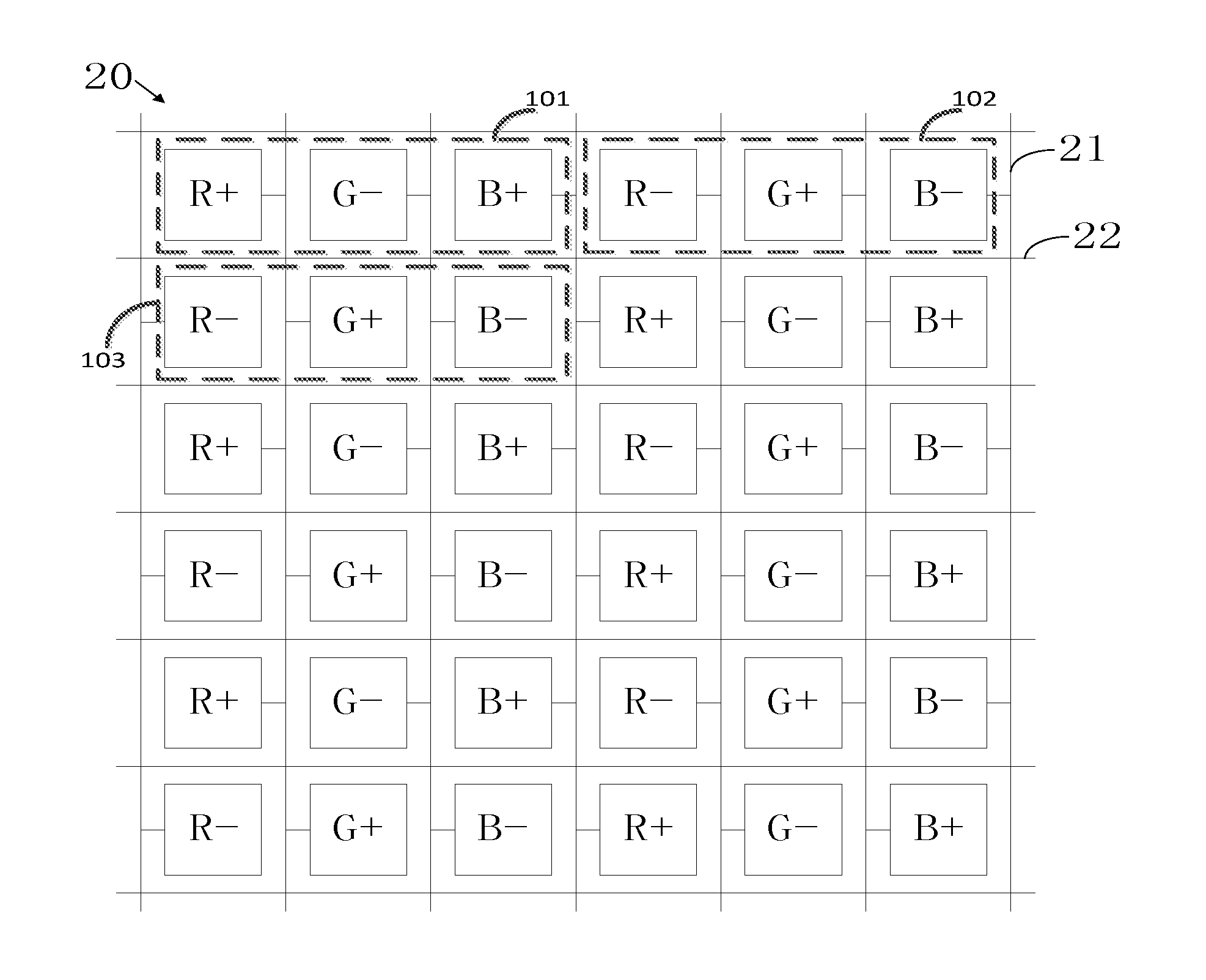
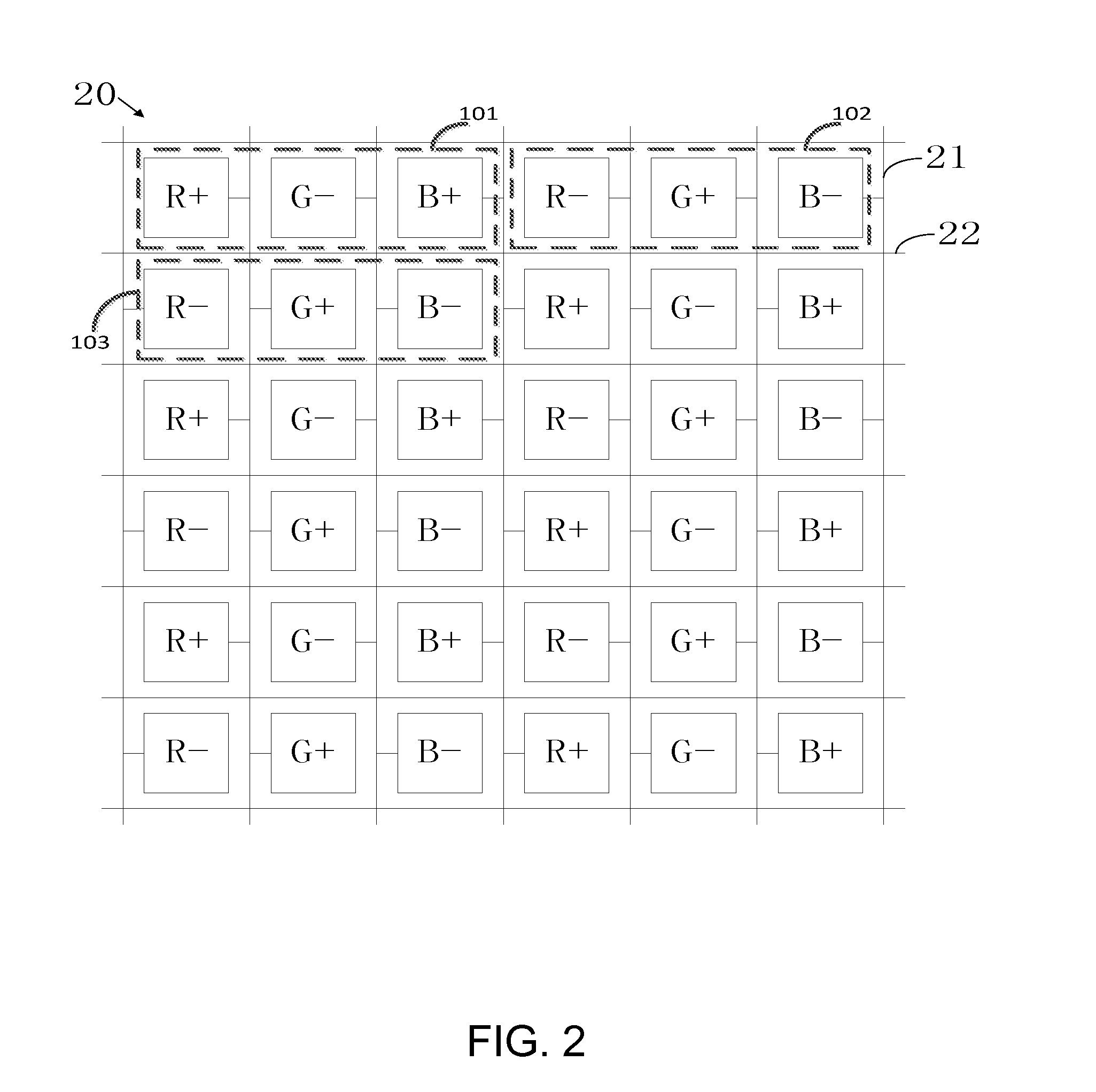
[0048]Refer to FIG. 2, which is a schematic structural view according to one embodiment of an LCD panel of the present invention.

[0049]The LCD panel of the present invention 20 includes an array substrate, and the array substrate include...


PUM


Abstract

An LCD panel and an LCD device are provided. The LCD panel includes all pixels respectively defined by a plurality of data lines and a plurality of the scanning lines to form a plurality of pixel columns and a plurality of pixel rows. All of the pixels in each column have the same color, and the two adjacent pixels in each pixel unit have opposite polarities. The pixels having the same color in two adjacent pixel units have opposite polarities, and each of the data lines is connected with the pixels with the same polarity.

Description

BACKGROUND OF THE INVENTION[0001]Field of the Invention[0002]The present invention relates to liquid crystal display (LCD) technology, and more particularly to an LCD panel and device thereof.[0003]Description of Prior Art[0004]Along with the continuous development of LCD devices, one of the main research directions in LCD panel has become how to let LCD panel have a better display performance.[0005]FIG. 1 is a schematic structural view according to a conventional LCD panel. The LCD panel 10 includes data lines 11, scanning lines 12, and a plurality of pixel rows and pixel columns defined by the data lines 11 and the scanning lines 12. The plurality of data lines 11 are configured for inputting data signals to a plurality of pixel rows, and the plurality of scanning lines 12 are configured for inputting scanning signal lines to a plurality of pixel columns. All pixels can be displayed on a screen in accordance with the corresponding data signals and the corresponding scanning signal...

Claims


Application Information

Patent Timeline
IPC IPC(8): G09G3/36G02F1/1368G09G3/00G02F1/1362
CPCG09G3/3607G02F1/136286G02F1/1368G09G3/003G09G2320/0247G09G3/3677G09G3/3688G02F2201/52G09G2320/0209G09G3/3618G02B30/00G09G3/3614G09G2310/0218G09G2340/0435
Inventor HE, TAOCHEN, YUYEH
Owner SHENZHEN CHINA STAR OPTOELECTRONICS TECH CO LTD
Why Eureka
Try Eureka