
Fault location of DC distribution systems

a technology of fault location and distribution system, applied in the direction of fault location, fault location by conductor type, instruments, etc., can solve the problems of failure to effectively implement the functionality of fault current limitation (fcl) and the fault location in dc power distribution system

Active Publication Date: 2016-12-01
ABB (SCHWEIZ) AG
View PDF3 Cites 17 Cited by
  • Summary
  • Abstract
  • Description
  • Claims
  • Application Information

AI Technical Summary

Benefits of technology

The patent describes a new system for locating faults in DC power distribution systems. The system uses special techniques to accurately detect and locate faults, which can help to improve the reliability and efficiency of these systems. The patent also includes methods for making and using the system, which can be adapted as needed. Overall, the invention provides a more effective way to manage and troubleshoot faults in DC power distribution systems.

Problems solved by technology

Present efforts at fault location in DC power distribution systems suffer from a number of shortcomings and disadvantages.
Existing proposals fail to effectively implement fault current limiting (FCL) functionality and to reduce the adverse impacts of high fault current on equipment within or coupled with the DC power distribution system and on the DC power distribution system itself.

Method used


Image

  • Fault location of DC distribution systems
  • Fault location of DC distribution systems
  • Fault location of DC distribution systems

Examples


Embodiment Construction

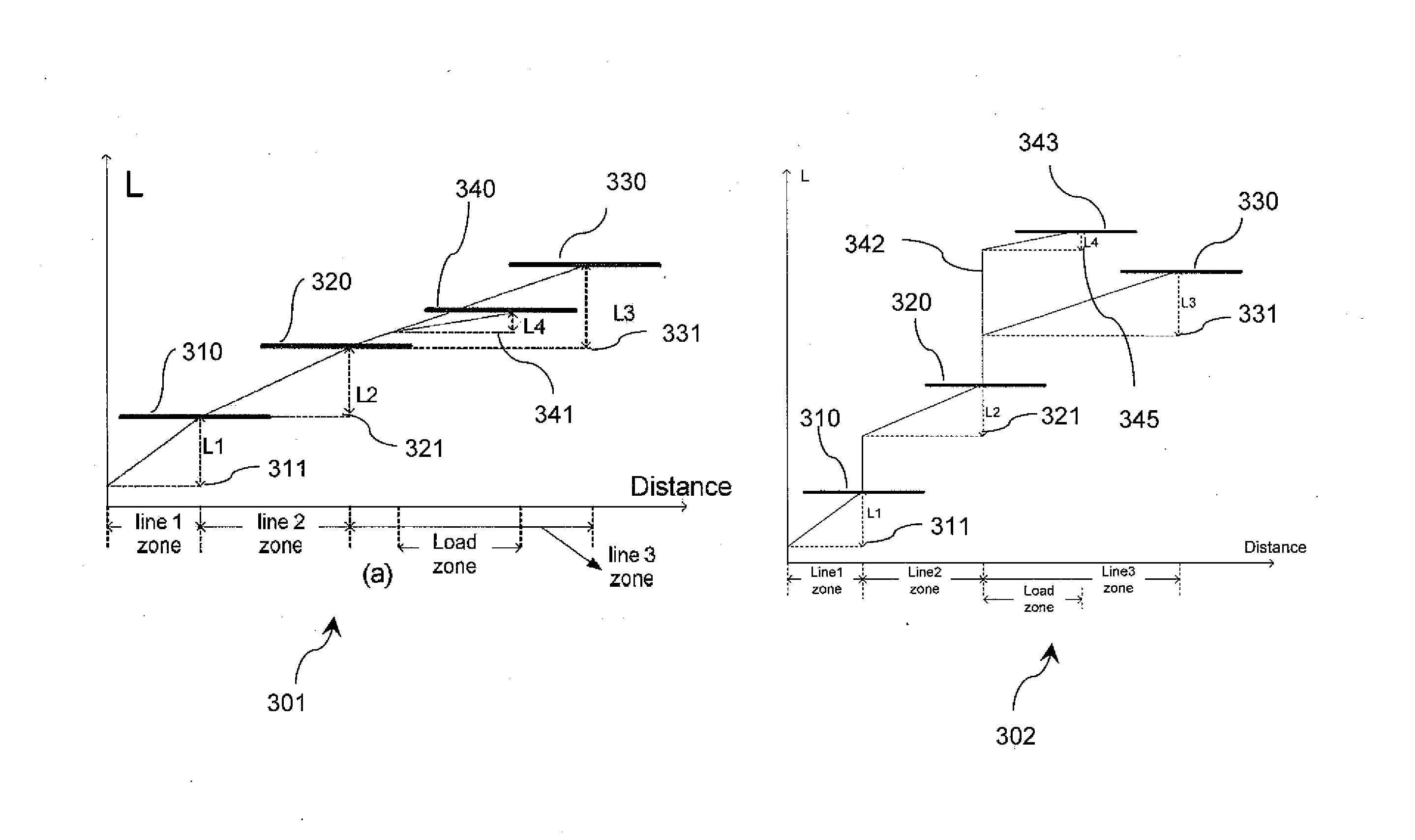
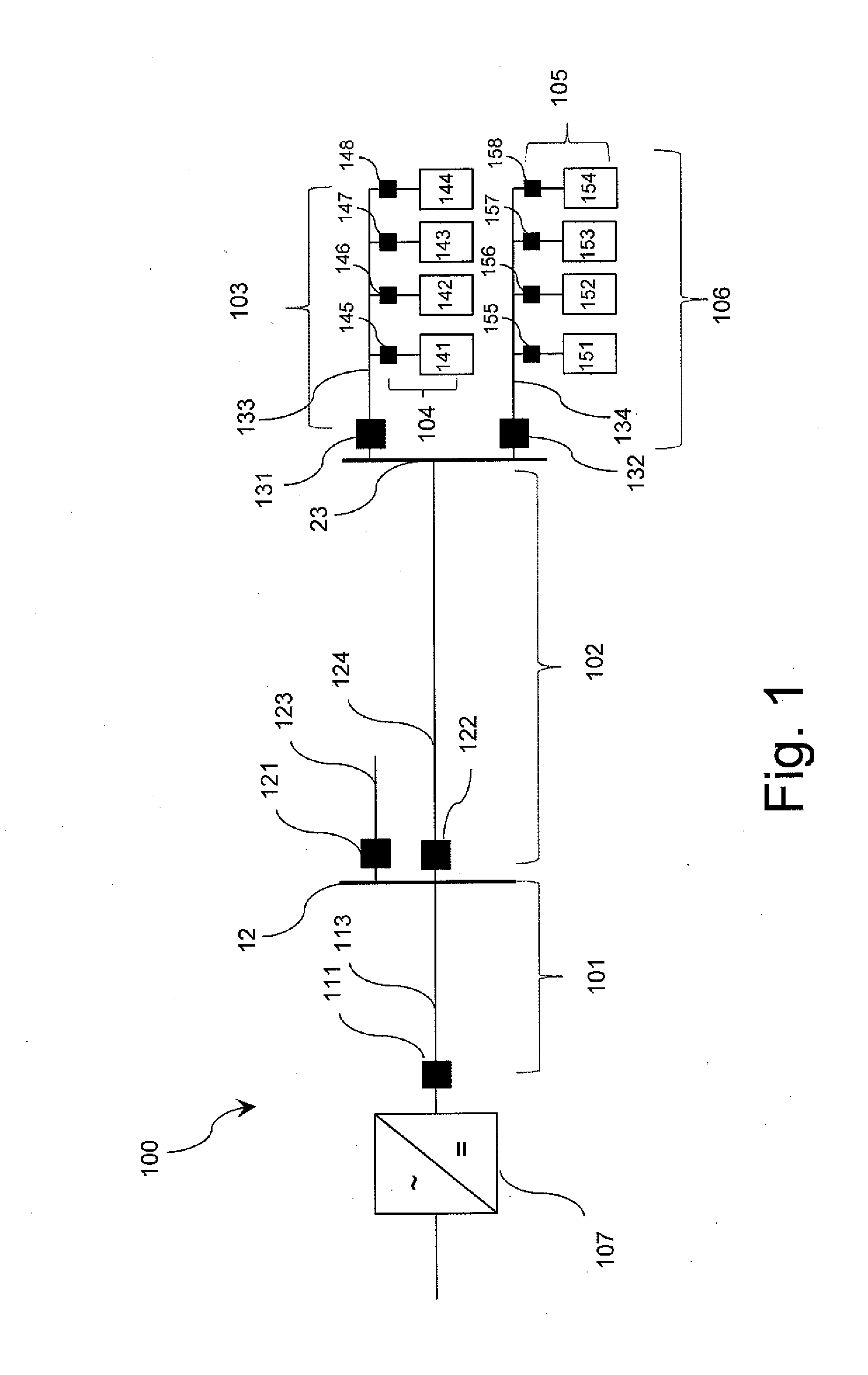
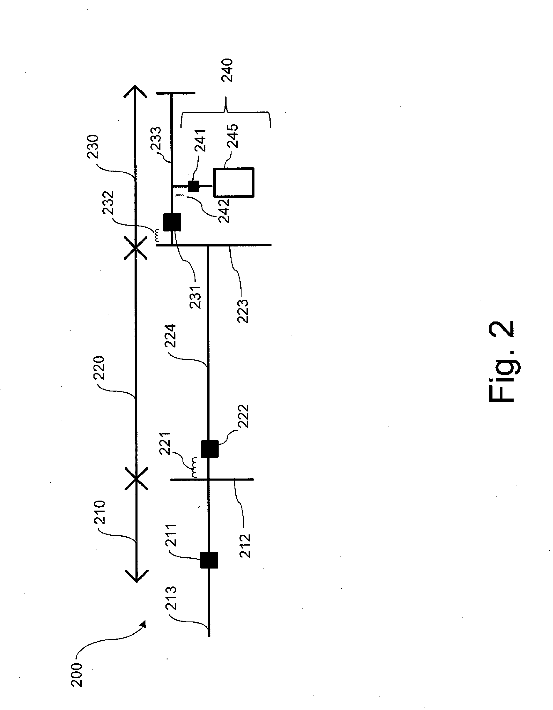
[0009]With reference to FIG. 1 there is illustrated an exemplary DC power distribution system 100. In the illustrated embodiment, DC power distribution system 100 is structured as a converter-based, tightly-coupled DC power distribution system. In other embodiments, system 100 may be structured as another type of DC power distribution system. It shall be appreciated that system 100 may be implemented in a variety of applications, including power distribution systems in naval and marine vessels, land vehicles, construction equipment, mining equipment, aircraft, factories, manufacturing or other industrial facilities, data centers and server farms to name but a few examples.

[0010]DC power distribution system 100 includes AC / DC converter 107 which is structured to receive AC power from a transmission line or generation source (not illustrated), convert the AC power to DC power, and provide DC power to DC power distribution system 100. System 100 includes a plurality of protection zones...


PUM


Abstract

Unique systems, methods, techniques and apparatuses of fault location in DC power distribution systems are disclosed. One exemplary embodiment is a DC power distribution system including a plurality of zones each including a DC power distribution line and a protective device. Each protective device structured to sense one or more electrical characteristics of a line and to controllably open a circuit including the line. At least one intelligent electronic device is structured to determine a line inductance based upon electrical characteristics sensed by one or more of the protective devices and to evaluate a location of the line fault based upon the determined line inductance.

Description

BACKGROUND[0001]The present disclosure relates generally to fault location in DC distribution systems, sometimes referred to as DC distribution networks. Recent improvement in energy and power density of power electronic switches has facilitated development of DC power distribution systems. Present efforts at fault location in DC power distribution systems suffer from a number of shortcomings and disadvantages. Existing proposals fail to effectively implement fault current limiting (FCL) functionality and to reduce the adverse impacts of high fault current on equipment within or coupled with the DC power distribution system and on the DC power distribution system itself. There remain unmet needs respecting identification of fault location, speed of fault protection, comprehensive coverage of protected system zones, reliability, minimization of communication delay, and local measurement of fault conditions and fault characteristics. Further unmet needs include enhancing protection se...

Claims


Application Information

Patent Timeline
Patent Type & Authority Applications(United States)
IPC IPC(8): H02H3/10
CPCH02H3/10G01R31/086H02H3/38H02H3/445H02H7/268G01R31/088Y04S10/52
Inventor QI, LIFENG, XIANYONGPAN, JIUPING
Owner ABB (SCHWEIZ) AG
Learn More