Sole structure for shoes

a technology for shoes and soles, applied in the field of shoe sole structure, can solve problems such as user discomfort, and achieve the effect of less likely discomfor

Active Publication Date: 2016-12-08
MIZUNO CORPORATION
View PDF15 Cites 20 Cited by
  • Summary
  • Abstract
  • Description
  • Claims
  • Application Information

AI Technical Summary

Benefits of technology

[0017]According to the sole structure for shoes according to the present invention, uncomfortableness can be less likely e

Problems solved by technology

When a user who lands on the lateral side of the metatarsus portion runs in shoes provided with the sole structure described in Japanese Patent No. 3403952,

Method used


Image

  • Sole structure for shoes
  • Sole structure for shoes
  • Sole structure for shoes

Examples


Embodiment Construction

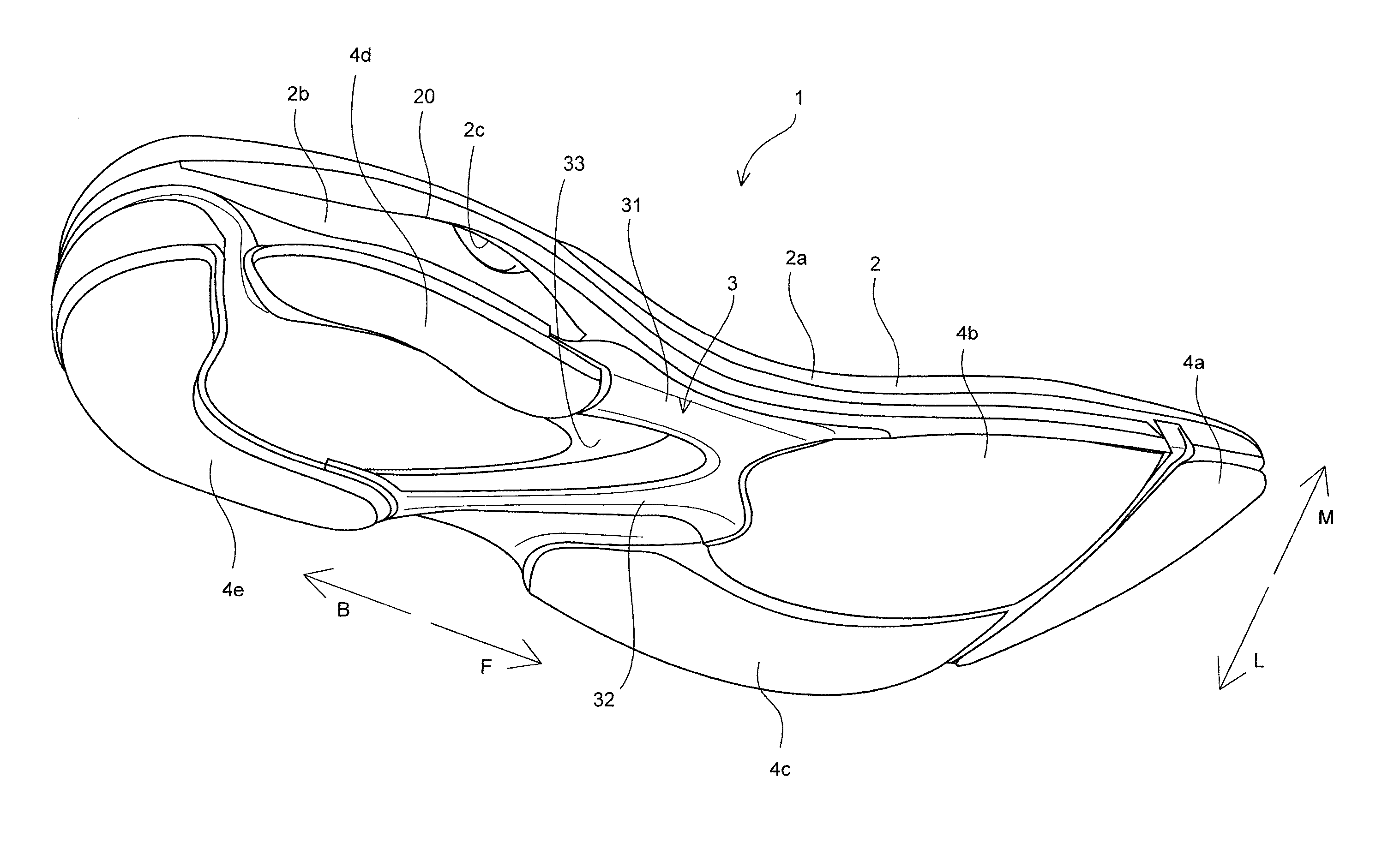
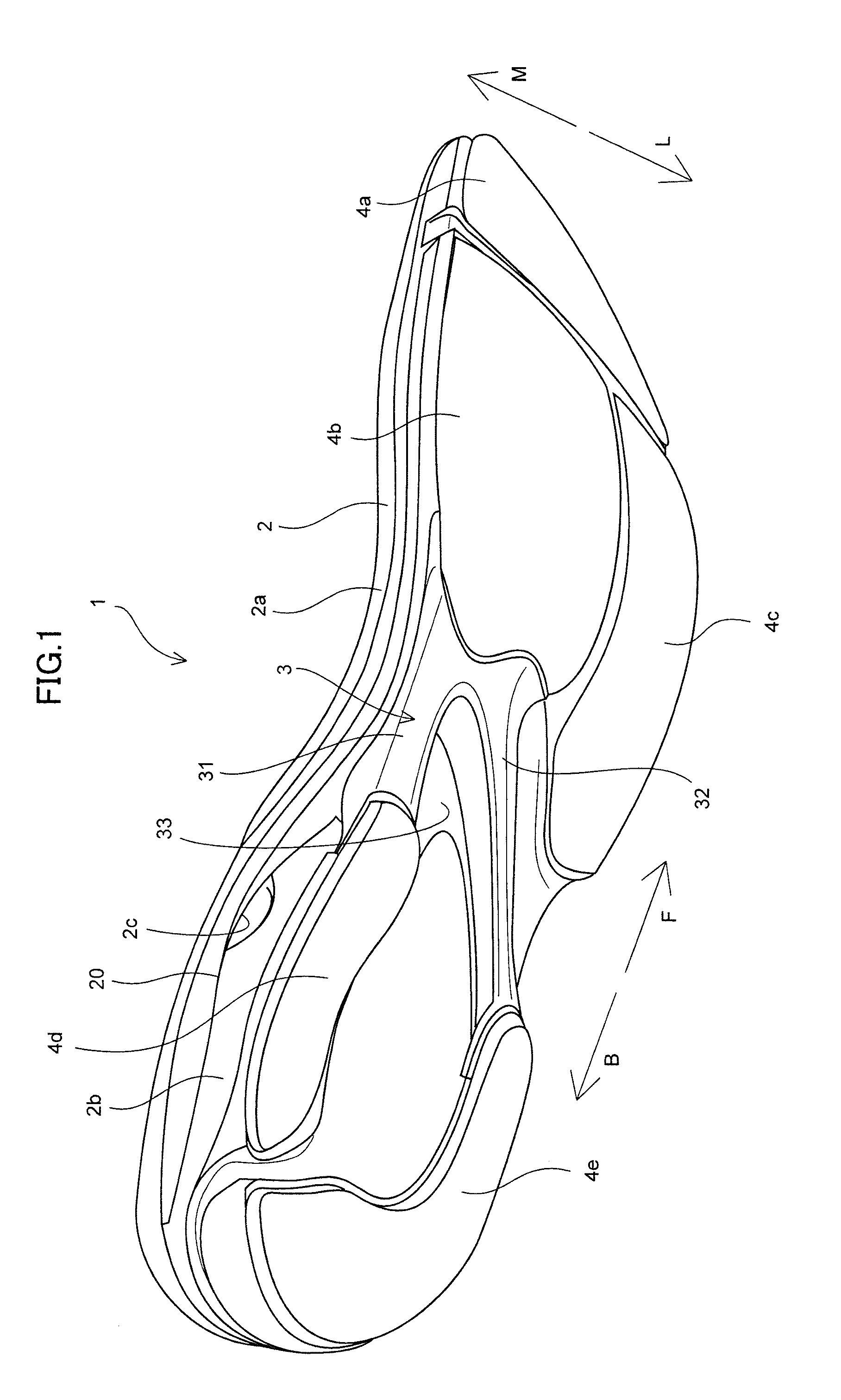
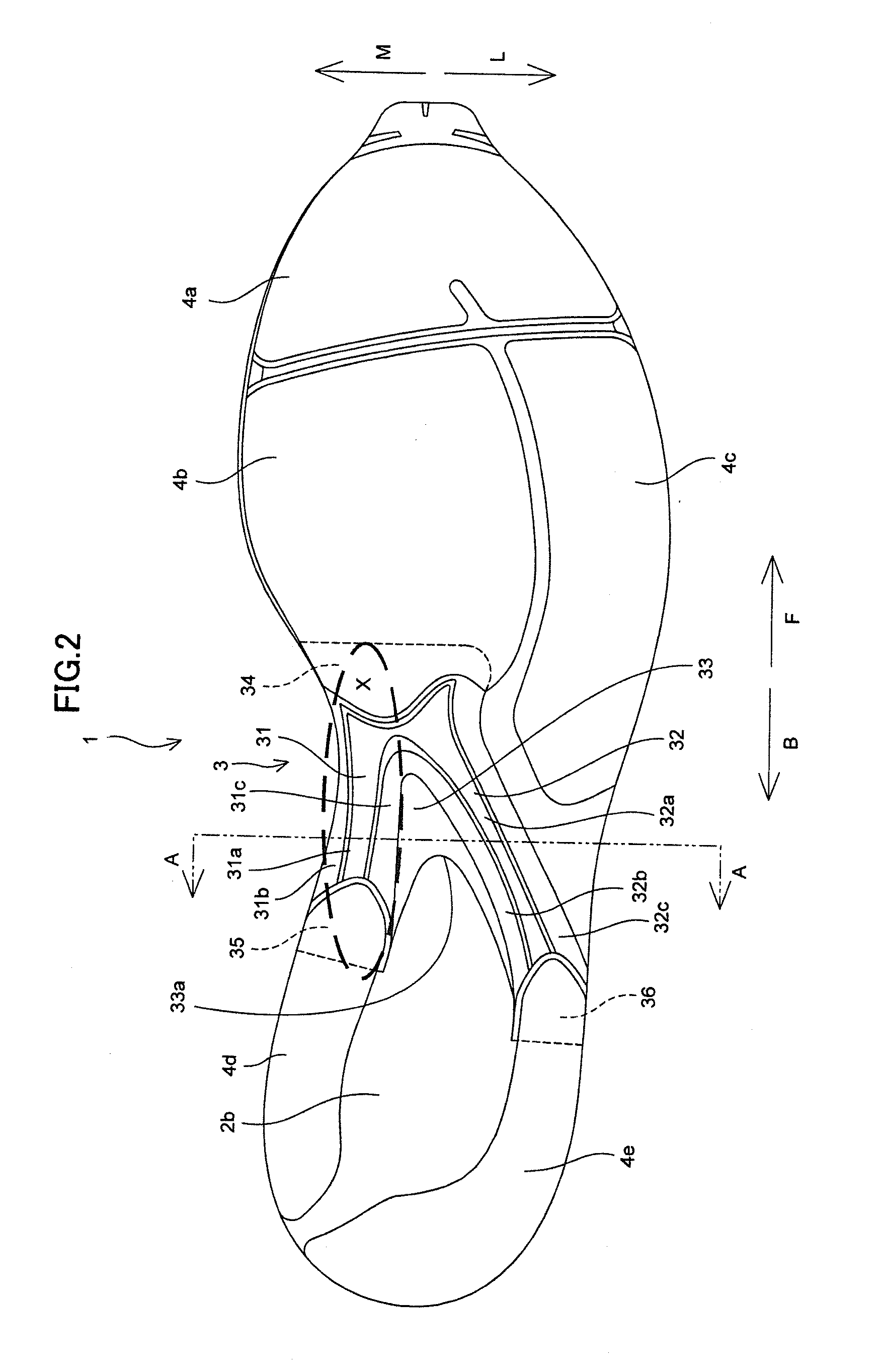
[0025]A sole structure 1 for shoes according to one embodiment of the present invention will be described with reference to FIGS. 1 to 6.

[0026]As shown in FIGS. 1 and 2, sole structure 1 for shoes includes a midsole 2, a plate member 3 made of a hard resin harder than midsole 2, which is joined to a lower surface of midsole 2, and a plurality of outsoles 4a to 4e for plate member 3 joined to the lower surface of midsole 2.

[0027]Midsole 2 is formed from a soft elastic member. For example, midsole 2 is composed of a thermoplastic resin such as an ethylene-vinyl acetate copolymer (EVA) or a foam thereof, a thermosetting resin such as polyurethane (PU) or a foam thereof, or a rubber material such as butadiene rubber or chloroprene rubber or a foam thereof. Midsole 2 has a midsole main body portion 2a extending from a forefoot portion to a heel portion and a heel midsole portion 2b provided in the heel portion and provided below midsole main body portion 2a as shown in FIGS. 1 and 3.

[002...


PUM

PropertyMeasurementUnit
Widthaaaaaaaaaa
Widthaaaaaaaaaa

Abstract

A sole structure for shoes includes a midsole and a plate member made of a hard resin harder than the midsole, which is joined to a lower surface of the midsole. The plate member includes a first reinforcement portion extending rearwardly from a position corresponding to a portion in the rear of a thenar of a user along a medial side arch region and a second reinforcement portion extending rearwardly on a lateral side from the position corresponding to the portion in the rear of the thenar of the user so as to avoid a position corresponding to a portion more frontward than a center of a fifth metatarsal bone.

Description

[0001]This nonprovisional application is based on Japanese Patent Application No. 2015-114386 filed with the Japan Patent Office on Jun. 5, 2015, the entire contents of which are hereby incorporated by reference.BACKGROUND OF THE INVENTION[0002]Field of the Invention[0003]The present invention relates to a sole structure for shoes and particularly to a sole structure for shoes including a midsole and a plate member made of a hard resin.[0004]Description of the Background Art[0005]A sole structure for shoes including a midsole and a plate made of a material harder than the midsole (a plate member made of a hard resin) has conventionally been known (Japanese Patent No. 3403952). The plate of the sole structure for shoes in Japanese Patent No. 3403952 is constituted of a corrugated heel portion provided under a heel, a medial side portion extending forward from a medial side front end of the heel portion of the plate along a medial side, and a lateral side portion extending forward fro...

Claims


Application Information

Patent Timeline
IPC IPC(8): A43B13/18A43B13/12A43B13/04A43B13/42
CPCA43B13/186A43B13/42A43B13/188A43B13/04A43B13/125A43B7/142A43B7/143A43B7/1445A43B13/12A43B13/146A43B13/16A43B13/181
Inventor TAKESHITA, TAKESHIDAZAI, TATSUYA
Owner MIZUNO CORPORATION
Why Eureka
Try Eureka