Marker Materials and Forms for Magnetic Marker Localization (MML)

a magnetic marker and material technology, applied in the field of medical detection, can solve the problems of logistical and scheduling difficulties between radiology and surgery departments, hook wires can migrate away from the site of lesion or become displaced, and achieve the effect of uniform magnetic respons

Active Publication Date: 2016-12-08
ENDOMAGNETICS LTD
View PDF0 Cites 22 Cited by
  • Summary
  • Abstract
  • Description
  • Claims
  • Application Information

AI Technical Summary

Benefits of technology

[0012]The invention relates to magnetic markers for surgical use. In particular, it relates to magnetic markers with a more uniform magnetic response once deployed than would be expected from their geometry prior to deployment.

Problems solved by technology

First, it involves two separate procedures, and can present logistical and scheduling difficulties between radiology and surgery departments.
Second, the positioning of the guidewire may not be optimal for achieving the desired cosmetic result in the subsequent surgery.
Third, the hook wire can migrate away from the site of the lesion or become displaced during mammography or moving the patient.
Fourth, the insertion of the wire can be painful for patients and finally, the risk of infection means that surgery usually needs to take place the same day as the wire insertion.
Although this removes the logistical complexity of WGL, the technique introduces the drawback of the use of radioactive materials, which require special handling and disposal procedures.
However, magnetic markers are relatively complex to manufacture compared with guide-wires.
In practice, these size constraints limit the magnetic response and in turn the ease with which the marker can be localised with a magnetic probe.
Another challenge for magnetic biopsy markers is that to achieve an effective magnetic response, the volume of material needs to be maximised.
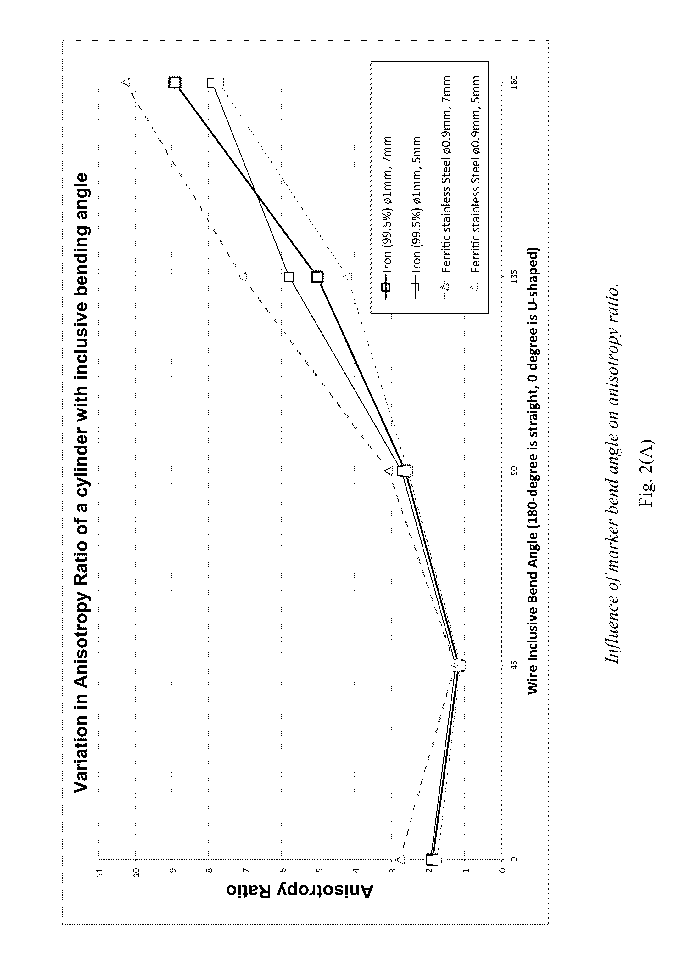
This aspect ratio results in a non-uniform magnetic response with a much stronger signal being obtained when the marker major axis is in line with a probe, and a weaker signal when the marker major axis is transverse to the probe.

Method used


Image

  • Marker Materials and Forms for Magnetic Marker Localization (MML)
  • Marker Materials and Forms for Magnetic Marker Localization (MML)
  • Marker Materials and Forms for Magnetic Marker Localization (MML)

Examples


Embodiment Construction

[0042]A method for making magnetic markers as permanent magnets is described in U.S. Pat. No. 6,173,715. Permanent magnet implants have the drawback that they will attract any magnetic material in the vicinity and therefore could interact undesirably with other implants, or move in the tissue, for example, when a surgical tool made from magnetic material is nearby.

[0043]A method for making markers formed from superparamagnetic iron oxide (SPIO) nanoparticles in bioabsorbable form is described in US Publication No. 2014 / 0314679. SPIO particles avoid the concerns that occur for permanent magnetic markers because such materials have no magnetic remanence, and are not magnetic in themselves, but only become magnetized when in the presence of a magnetic field. The detection and localization of these SPIO magnetic markers can be performed with a sensitive magnetometer (or susceptometer) that generates an alternating magnetic field to excite the marker magnetically, and detects the magneti...


PUM


Abstract

A magnetic marker for marking a site in tissue in the body. In one embodiment, the marker comprises a magnetic metallic glass. In another embodiment, the marker is in a non-spherical configuration having an anisotropy ratio less than 9. In yet another embodiment, the marker is in a non-spherical configuration having an anisotropy ratio less than 6. In yet another embodiment, the marker is in a non-spherical configuration having an anisotropy ratio less than 3.

Description

RELATED APPLICATIONS[0001]This application claims priority from U.S. Provisional Patent Application 62 / 170,768 filed on Jun. 4, 2015, the content of which is herein included by reference in its entirety.FIELD OF THE INVENTION[0002]The invention relates generally to the field of markers for medical detection and more specifically to magnetic medical markers.BACKGROUND OF THE INVENTION[0003]With the increasing prevalence of mammography screening programs, the majority of breast cancers are detected as small, non-palpable (or occult) lesions that are amenable to breast conserving treatment. Accurate localization of non-palpable breast cancers is key to allowing surgical removal of the complete tumor with adequate margins. If the tumor is not completely excised, patients need to undergo a further operation to remove any remaining cancerous tissue. Accurate localization also helps to avoid excision of excess breast tissue that could result in adverse cosmetic results. Accurate localizati...

Claims


Application Information

Patent Timeline
Patent Type & Authority Applications(United States)
IPC IPC(8): A61B90/00A61B5/00A61B5/05
CPCA61B90/39A61B5/05A61B2090/3987A61B2090/3954A61B2562/0223A61B5/4312H01F1/032H01F1/12A61B2090/3908A61B2090/3995A61B2017/00862A61B2090/3925A61B2090/3966
Inventor MAYES, ERICHARMER, QUENTIN JOHNLORIMER, KEVINPANKHURST, QUENTIN ANDREW
Owner ENDOMAGNETICS LTD
Why Eureka
Try Eureka