
Apparatus and method for stockpile control system

a technology of stockpile control and apparatus, which is applied in the direction of control devices for conveyors, conveyor parts, transportation and packaging, etc., can solve the problems of undetectable accuracy and impreciseness of conventional stockpile systems and methods, inability to repeat previous stockpile patterns, and inability to achieve the effect of reducing the number of users

Active Publication Date: 2016-12-08
KOLBERG PIONEER INC
View PDF6 Cites 6 Cited by
  • Summary
  • Abstract
  • Description
  • Claims
  • Application Information

AI Technical Summary

Benefits of technology

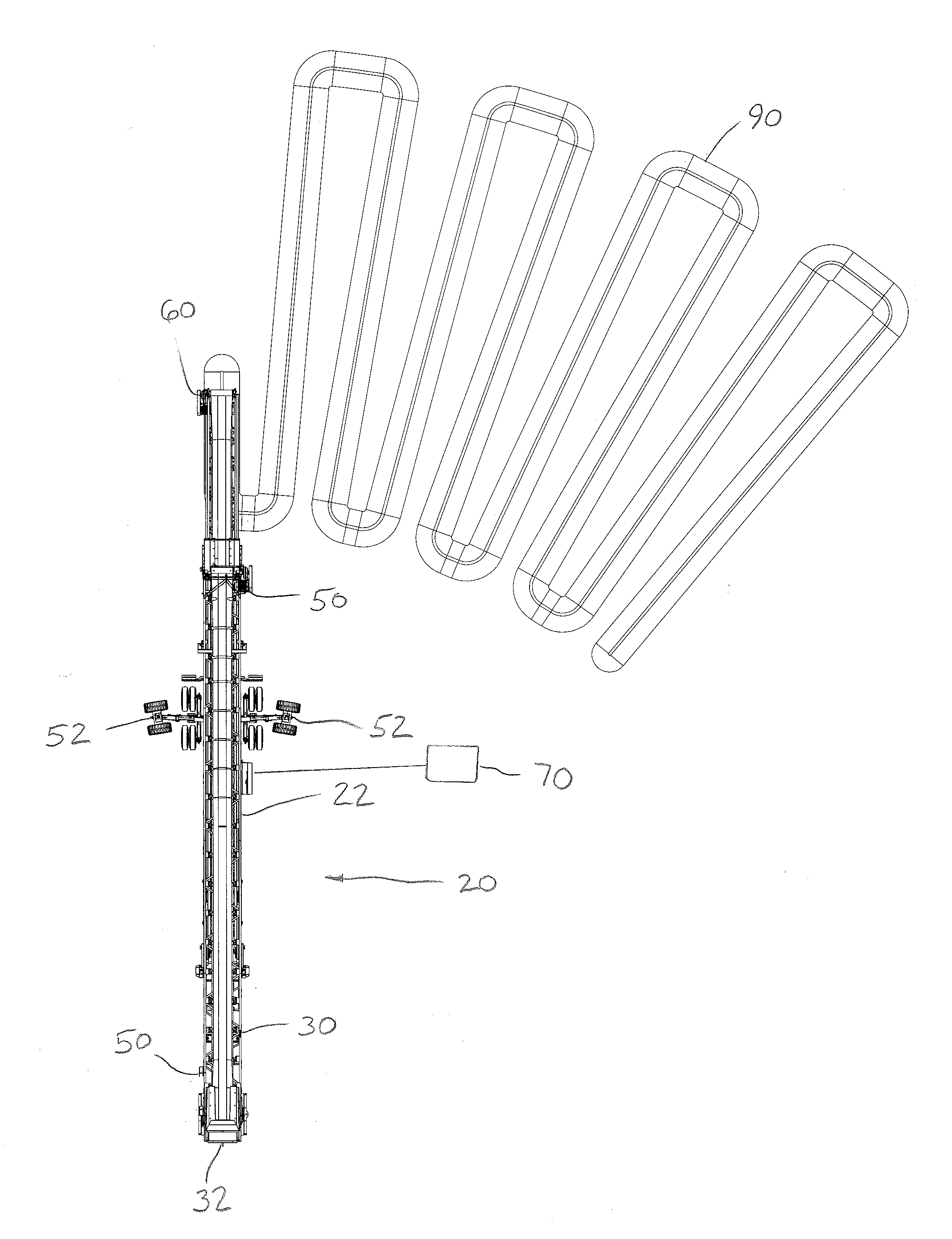
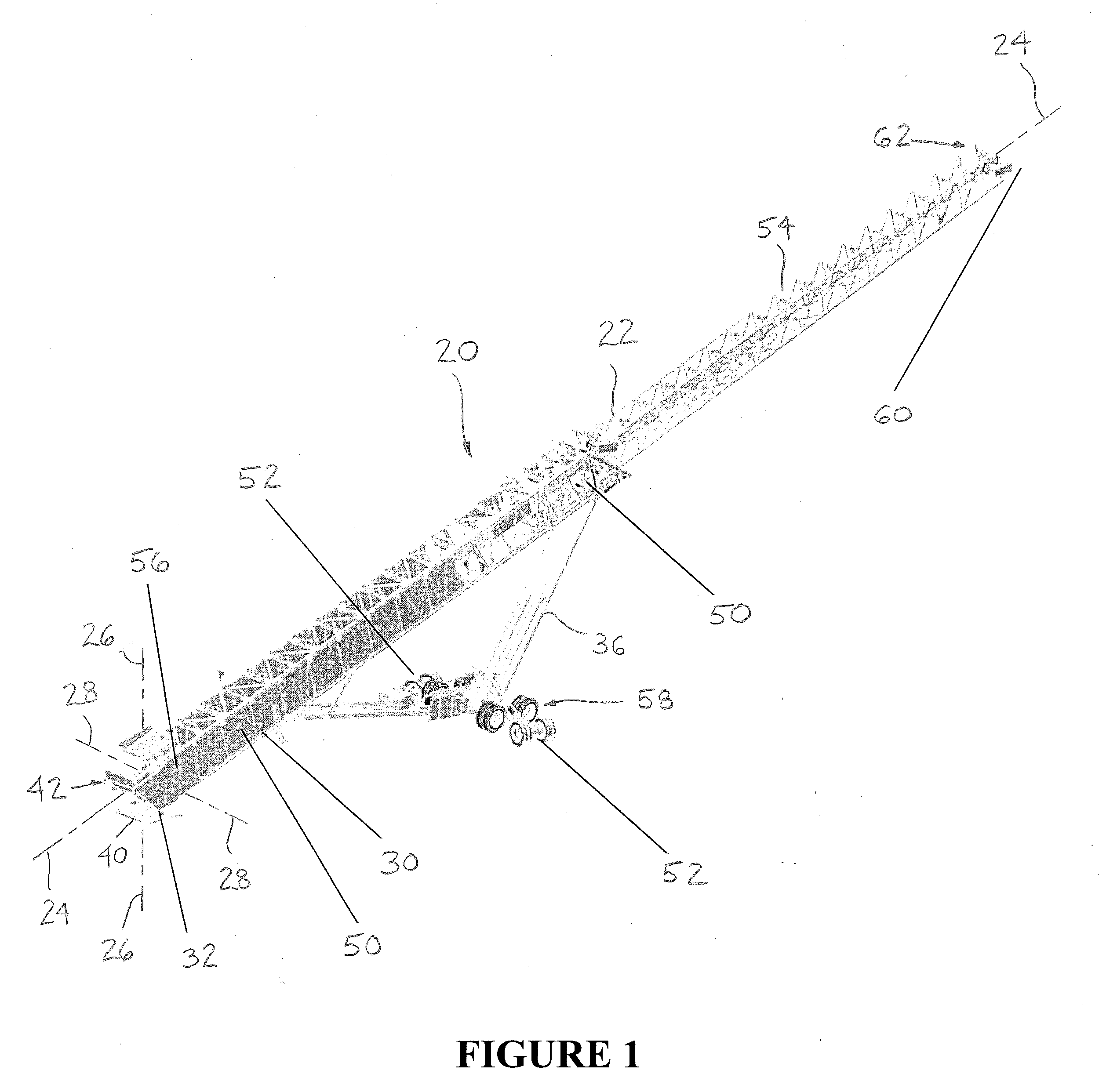
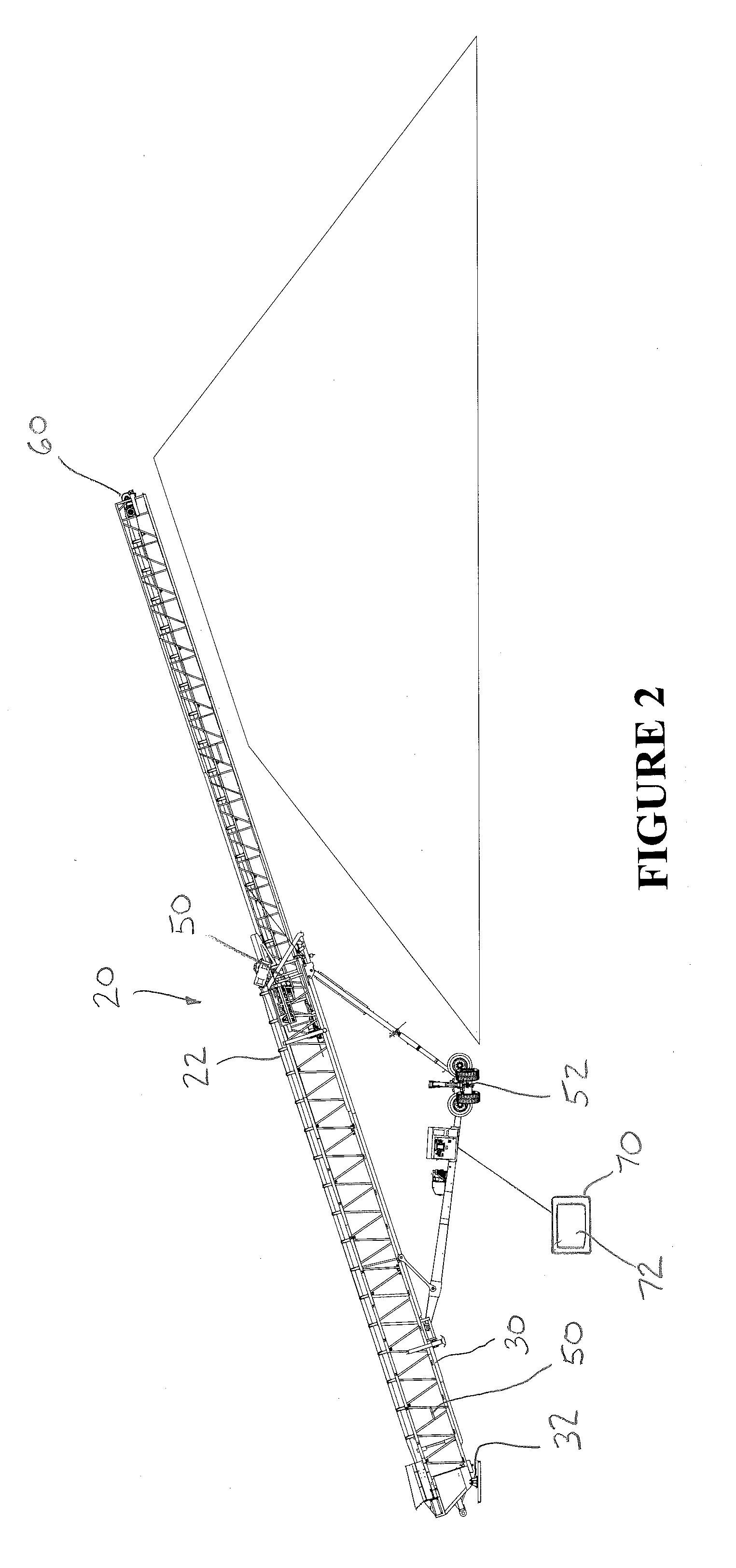
The invention is a system and method for controlling the production of a stockpile on a stockpile conveyor. The system includes a sensor, a limit switch, a pile probe, and a microprocessor. The sensor measures the location of the conveyor, the limit switch limits its movement, the pile probe measures the distance between the conveyor and the stockpile, and the microprocessor controls the movement of the conveyor. The method also includes calculating the boundaries of the stockpile and controlling the movement of the conveyor. The technical effects of this system and method are improved control over the production of a stockpile, allowing for more efficient and accurate inventory management.

Problems solved by technology

Conventional systems and methods, however, suffer from one or more disadvantages.
For example, conventional stockpile systems and methods are undesirably inaccurate and imprecise in terms of placing and locating a stockpile.
Conventional stockpile systems and methods also do not permit the user to repeat previous stockpile patterns.
Conventional stockpile systems and methods are also difficult to use.
Conventional stockpile systems and methods also do not sufficiently calculate and control the boundaries of the stockpile and the movement of the stockpile conveyor.
In addition, conventional stockpile systems and methods do not maximize stockpile capacity or stockpile desegregation.

Method used


Image

  • Apparatus and method for stockpile control system
  • Apparatus and method for stockpile control system
  • Apparatus and method for stockpile control system

Examples


Embodiment Construction

[0005]Accordingly, it is an advantage of the preferred embodiments of the invention claimed herein to provide an apparatus and method for a stockpile control system that accurately and precisely places and locates stockpiles. It is also an advantage of the preferred embodiments of the invention claimed herein to provide an apparatus and method for a stockpile control system that is allows the user to repeat stockpile patterns. It is another advantage of the preferred embodiments of the invention claimed herein to provide an apparatus and method for a stockpile control system that is easy to use. It is a further advantage of the preferred embodiments of the invention claimed herein to provide an apparatus and method for a stockpile control system that determines the equipment location using one or more sensors and computer-based software. It is a still further advantage of the preferred embodiments of the invention claimed herein to provide an apparatus and method for a stockpile con...


PUM


Abstract

A stockpile control system adapted for use on a stockpile conveyor comprising a sensor that is disposed on the stockpile conveyor, a limit switch that is disposed on the stockpile conveyor, a pile probe that is disposed on the stockpile conveyor, and a microprocessor that is in operative communication with the limit switch and the sensor. The stockpile conveyor is adapted to move, the sensor is adapted to measure the location of the stockpile conveyor, the limit switch is adapted to limit the movement of the stockpile conveyor, the pile probe is adapted to measure a distance between the stockpile conveyor and a stockpile, and the microprocessor is adapted to control the movement of the stockpile conveyor. A method for controlling the production of a stockpile comprising providing a stockpile control system, calculating one or more stockpile boundaries, and controlling the movement of the stockpile conveyor.

Description

CROSS-REFERENCES TO RELATED APPLICATIONS / PATENTS[0001]This application relates back to and claims the benefit of priority from U.S. Provisional Application for Patent Ser. No. 62 / 171,736 titled “Stockpile System” and filed on Jun. 5, 2015.FIELD OF THE INVENTION[0002]The present invention relates generally to systems and methods for controlling items of equipment, and particularly to systems and methods for controlling stockpile equipment.BACKGROUND AND DESCRIPTION OF THE PRIOR ART[0003]It is known to use equipment to produce stockpiles. Conventional systems and methods, however, suffer from one or more disadvantages. For example, conventional stockpile systems and methods are undesirably inaccurate and imprecise in terms of placing and locating a stockpile. Conventional stockpile systems and methods also do not permit the user to repeat previous stockpile patterns. Conventional stockpile systems and methods are also difficult to use. In addition, conventional stockpile systems and m...

Claims


Application Information

Patent Timeline
Patent Type & Authority Applications(United States)
IPC IPC(8): B65G43/00B65G41/00B65G43/08B65G21/14
CPCB65G43/00B65G43/08B65G41/008B65G21/14B65G41/002
Inventor ENGE, KEITHWESTERMAN, MARK
Owner KOLBERG PIONEER INC
Learn More