
Optical connector

Inactive Publication Date: 2016-12-08
FUJITSU COMPONENENT LTD
View PDF15 Cites 11 Cited by
  • Summary
  • Abstract
  • Description
  • Claims
  • Application Information

AI Technical Summary

Benefits of technology

The invention prevents the ferrule boot from disconnecting.

Problems solved by technology

Excessive bending of an optical waveguide degrades the optical transmission characteristics thereof.
Upon the disconnection of the ferrule boot from the lens ferrule, the optical waveguide is not properly protected, and may cause the optical transmission loss.

Method used


Image

  • Optical connector
  • Optical connector
  • Optical connector

Examples


Embodiment Construction

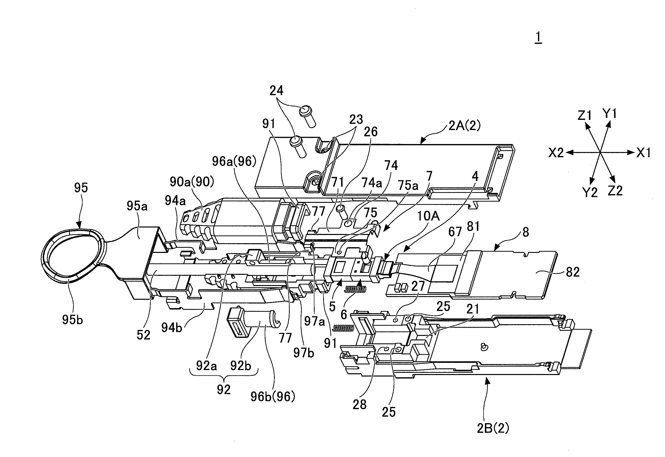
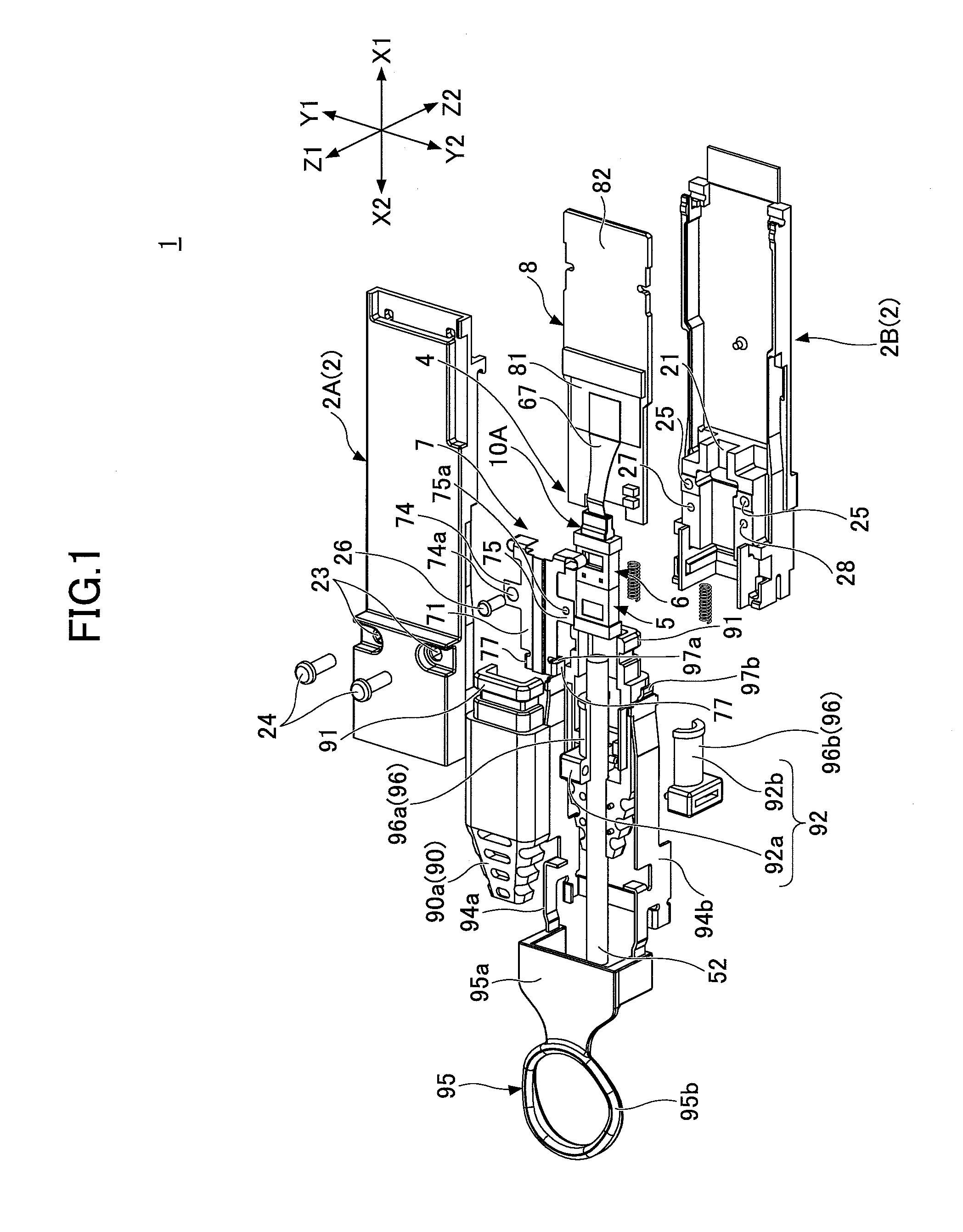
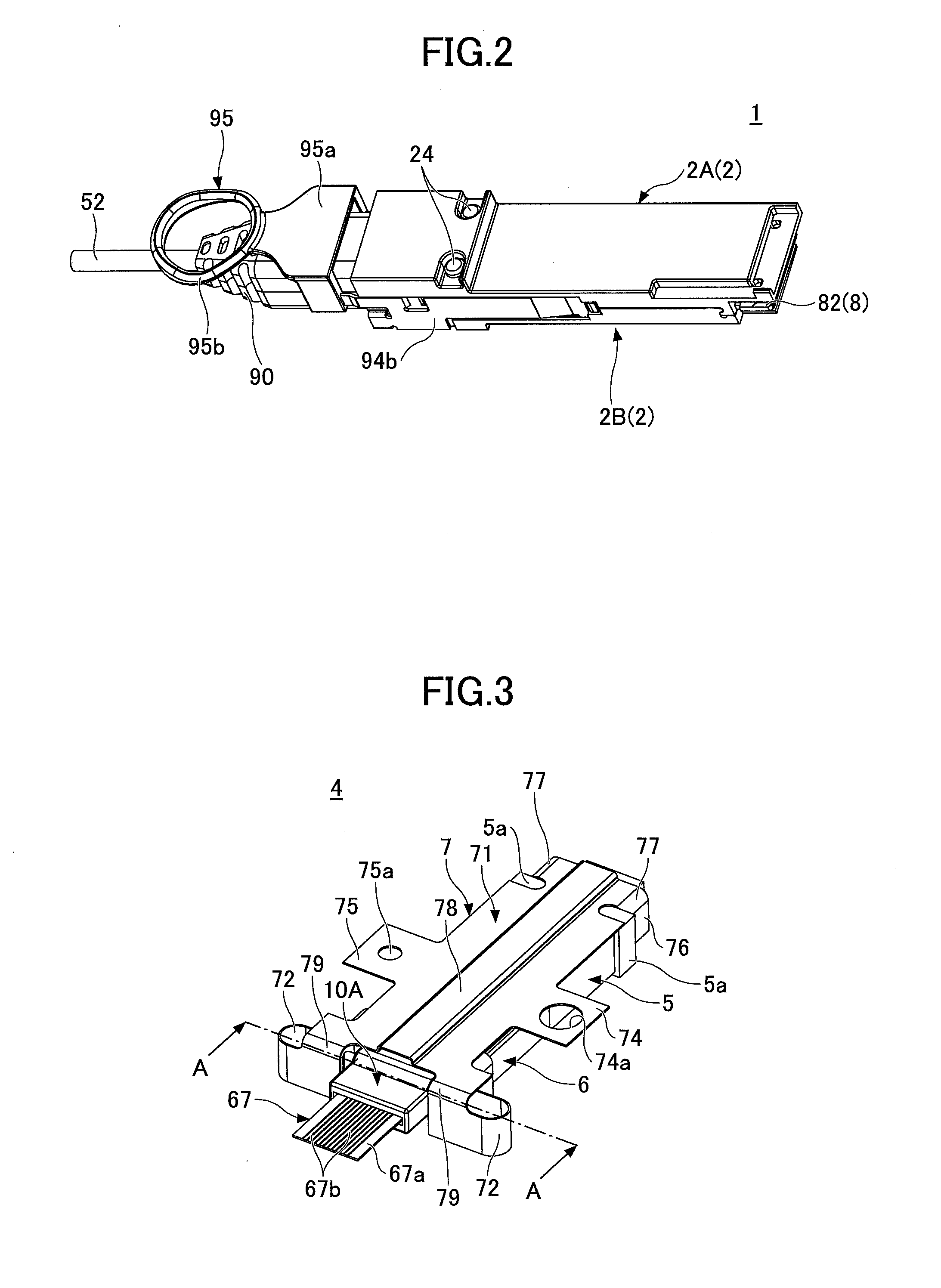
[0028]In the following, various non-limiting embodiments of the present invention will be described with reference to the accompanying drawings.

[0029]In illustrations provided in the drawings, the same or corresponding members or elements are referred to by the same or corresponding numerals, and duplicate descriptions thereof will be omitted. Further, the drawings are not provided for the purpose of illustrating size ratios between members or elements unless otherwise specified. Specific sizes may be determined by those skilled in the art by referring to the non-limiting embodiments that will be described hereinafter.

[0030]Further, the embodiments that will be described hereinafter are examples only that do not limit the invention. Features and combinations thereof described in these embodiments may not necessarily be essential to the invention.

[0031]In the following description, the direction indicated by arrows X1 and X2 is referred to as a contact direction. The direction indica...


PUM


Abstract

An optical connector includes a ferrule, an optical waveguide attached to the ferrule, and a boot attached to the ferrule to protect the optical waveguide, wherein the boot includes a cover part that covers the ferrule.

Description

BACKGROUND OF THE INVENTION[0001]1. Field of the Invention[0002]The disclosures herein relate to an optical connector.[0003]2. Description of the Related Art[0004]A recent increase in the volume of optical communication has resulted in a demand for increased packaging density of optical connectors. A small-size optical connector of a QSFP (Quad Small Form-Factor Pluggable) type, for example, has both an MT (mechanically transferable) ferrule that allows multiple optical fibers or the like to be connected in a lump and a lens ferrule that is connected to an optical waveguide coupled to a photoelectric conversion device. The MT ferrule and the lens ferrule are brought into fact-to-face contact with each other so as to establish a connection between an optical cable coupled to the MT ferrule and the optical waveguide coupled to the lens ferrule.[0005]Excessive bending of an optical waveguide degrades the optical transmission characteristics thereof. To prevent this, a ferrule boot for ...

Claims


Application Information

Patent Timeline
IPC IPC(8): G02B6/38
CPCG02B6/3851G02B6/387G02B6/3853G02B6/3861G02B6/3885G02B6/4206G02B6/4284G02B6/4292
Inventor MORIYAMA, SATOSHIDAIKUHARA, OSAMU
Owner FUJITSU COMPONENENT LTD
Learn More